
Automatic feeding system for producing optical cables

An automatic feeding and optical cable technology, applied in the direction of optics, light guides, optical components, etc., can solve the problems of poor control stability, poor extrusion, termination, etc., to ensure the stability of feeding, avoid management confusion, and reduce irrelevant operations Effect

Inactive Publication Date: 2016-11-16
宏安集团有限公司
View PDF11 Cites 9 Cited by
  • Summary
  • Abstract
  • Description
  • Claims
  • Application Information

AI Technical Summary

Problems solved by technology

Using this method, if there is an abnormality in the alarm device, but the personnel do not check and find it in time, it will cause a sudden interruption of the extrusion process or poor extrusion, resulting in a large number of substandard products, and even lead to the termination of production, resulting in the loss of a large number of raw and auxiliary materials. waste and loss; in addition, when using this method of feeding, it is generally necessary to stack the purchased raw materials around the production site, making the production site dirty and messy, affecting the hygiene management of the production site, and posing a risk of fire; at the same time, this method The feeding process usually uses other lifting equipment such as forklifts or cranes. Using such equipment at the production site can easily cause safety accidents for personnel and equipment, and there are great potential safety hazards; moreover, this feeding method is easy to operate. Complex and cumbersome, waste of manpower, material resources and other resources, poor control stability, raw materials are easily polluted, affecting product quality

Method used


Image

  • Automatic feeding system for producing optical cables

Examples


Embodiment

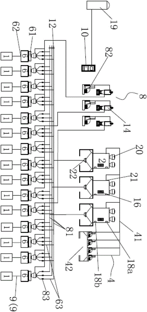
[0033] like figure 1 As shown, this embodiment discloses an automatic feeding system for optical cable production, which automatically supplies raw materials to the optical cable production line through program control; including:

[0034] Several storage tanks 2, each of which has a first feed port 21 and a first discharge port 22, the raw materials in the warehouse are transported from the first feed port 21 into the respective storage inside tank 2;

[0035] The first conveying mechanism 4 has a first feeding pipe 41 connecting the warehouse and each storage tank 2, and a vacuum suction device 42. The vacuum suction device 42 uses negative pressure to move the raw materials in the warehouse through the first feeding pipe 41 Suction feeding into each of the storage tanks 2;

[0036] Several material storage tanks 6, each of the material storage tanks 6 has a second material inlet 61 and a second material outlet 62, the second material inlet 61 communicates with the first m...


PUM


Abstract

The invention provides an automatic feeding system for producing optical cables. The automatic feeding system comprises a plurality of storage tanks and a plurality of storage buckets, wherein raw materials in a warehouse are sucked and conveyed to respective storage tanks by a first conveying mechanism by utilizing negative pressure; the raw materials in the storage tanks are sucked and conveyed to respective storage buckets by a second conveying mechanism by utilizing negative pressure; the raw materials in the storage buckets are extruded by virtue of screws and are conveyed to extrusion dies of optical cable production lines by a third conveying mechanism; one storage bucket is correspondingly arranged on one optical cable production line, one second feeding pipe is correspondingly arranged on one storage tank, all of the storage buckets communicate with all second feeding pipes by virtue of independent feeding branch pipes, regulating valves are respectively arranged on the feeding branch pipes, which storage tanks communicating with the storage buckets are respectively controlled by the regulating valves, and the feeding speed from the storage tanks to the storage buckets is regulated by virtue of the regulating valves. According to the automatic feeding system, full-automatic feeding for producing the optical cables is realized, the maintenance problem of production sites is solved, manpower and materials are saved, and the waste of the raw materials is avoided.

Description

technical field [0001] The invention relates to a feeding system, in particular to an automatic feeding system for optical cable production. Background technique [0002] In the production process of optical cables, the secondary sheathing and outer sheathing processes all need to go through the extrusion molding process. With the continuous production, the extrusion process requires continuous supply of raw materials to ensure the normal production of optical cable products. At present, the material supply of the extrusion molding process is mainly through the limit alarm reminder of the barrel, relying on the personnel to actively feed the material, so as to realize the continuity of the extrusion molding process. Using this method, if there is an abnormality in the alarm device, but the personnel do not check and find it in time, it will cause a sudden interruption of the extrusion process or poor extrusion, resulting in a large number of substandard products, and even l...

Claims


Application Information

Patent Timeline
IPC IPC(8): B29C47/10B29C47/92G02B6/44B29C48/92
CPCB29C48/287B29C48/297B29C48/298B29C48/92B29C2948/92828G02B6/4486
Inventor 张桂林
Owner 宏安集团有限公司
Learn More