Plastic extruders for the production of biodegradable mulches

A technology for degrading mulch and plastics, applied in the field of plastic extruders, can solve the problems of narrow temperature deviation range, material is not easy to melt, long heating time, etc., to achieve the effect of small deviation range, increased range and range of movement, and uniform temperature

Active Publication Date: 2018-09-18
GUANGDONG JINMING MACHINERY
View PDF2 Cites 0 Cited by
  • Summary
  • Abstract
  • Description
  • Claims
  • Application Information

AI Technical Summary

Problems solved by technology

[0006] 1. Most of the heat of plastic melting comes from the inner surface of the barrel, but when the plastic runs along the barrel of the extruder, some materials keep in contact with the inner surface of the metal barrel for a long time and run against the wall, so the heating time Longer; and some other materials are less in contact with the inner surface of the metal barrel during most of the time during the operation of the barrel, and the heating time is shorter; because some materials are heated for a longer time, while some materials are heated for a longer time. Short, so there is a phenomenon of temperature inhomogeneity between parts of the plastic material, which is acceptable for ordinary plastic materials (because they are less sensitive to temperature deviations, or they can can withstand a wide range of temperature deviations), but it is difficult for plastic raw materials for the production of degradable mulches (because they are sensitive to temperature deviations, or they can withstand a narrow range of temperature deviations)
[0007] 2. In the production of degradable plastic film, in order to avoid the problem of burning, the temperature of the barrel can usually only be set at a low level, which makes it difficult for the material to melt completely. When the material is transported to the barrier section, the material that has not been completely melted (small particles) The proportion of the material) is often too large, and the barrier section of the traditional extrusion screw lacks the function of further melting the small granular material

Method used


Image

  • Plastic extruders for the production of biodegradable mulches
  • Plastic extruders for the production of biodegradable mulches
  • Plastic extruders for the production of biodegradable mulches

Examples


Embodiment Construction

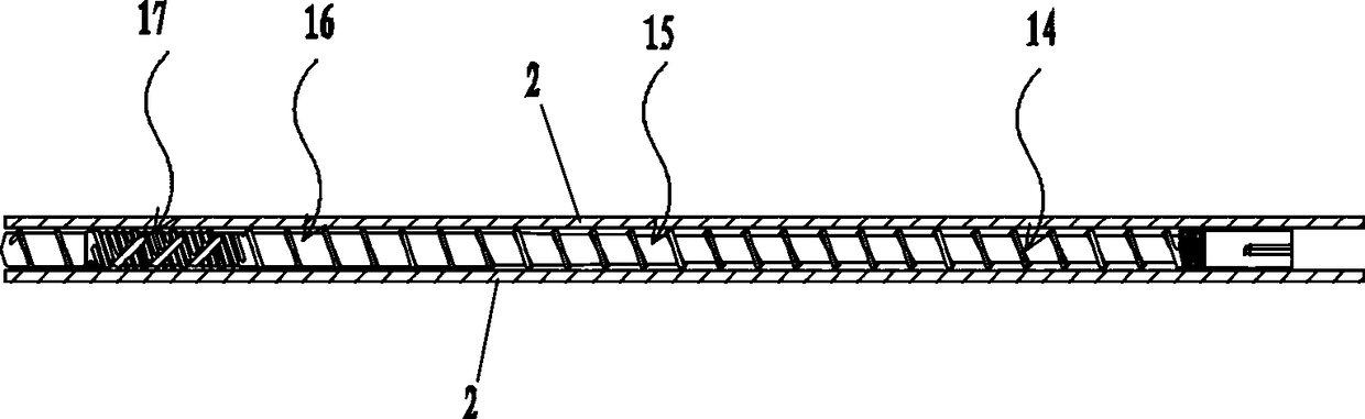
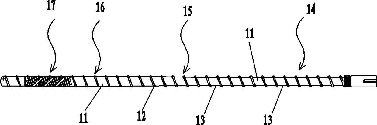
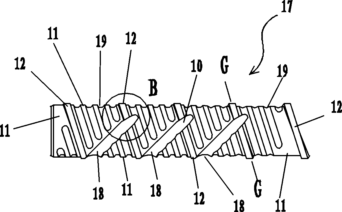
[0024] The plastic extruder used to produce degradable mulch film of this embodiment comprises barrel 2 and screw rod, figure 1 , figure 2 , image 3 , Figure 4 , Figure 5 , Figure 6 As shown, the screw rod includes a strip-shaped circular rod body 11, a helically extended flight 12, and the screw flight 12 protrudes outwards relative to the circumferential surface of the circular rod body, and the sides of the screw flight 12 (such as Figure 7 The side shown by the midline segment mn) is close to the inner surface of the barrel 2, and an annular gap is formed between the surface of the circular rod body 11 and the inner surface of the barrel 2, and the annular gap is separated by a screw edge to form a screw groove 13 The screw rod is divided into feeding section 14, compression section 15, homogenization section 16, and barrier section 17 from back to front, wherein the screw groove depth of feeding section 14 remains constant, and the screw groove depth of compress...


PUM


Abstract

A plastic extruder for producing degradable plastic films comprises a material barrel and a screw rod. A plurality of secondary reverse screwing grooves are further formed in the surface of a round rod body of the shield section of the screw rod, the secondary reverse screw grooves are concave inwards relative to the circumferential surface of the round rod body, and the spiral direction of the secondary reverse screwing grooves and the spiral direction of a screw flight are opposite. Each secondary reverse screwing groove only has one intersection point with the screw flight, and the screw flight is broken at the intersection point to form a screw flight notch; the secondary reverse screwing grooves keep continuously extending at the intersection point to pass over the screw flight notch, and the widths of the screw flight notches are gradually decreased from front to back. A plurality of secondary forward screwing grooves are further formed in the surface of the round rod body of the shield section of the screw rod. According to the plastic extruder for producing degradable plastic films, all the parts of fluid can be fully stirred on the shielding section, the temperature of all the parts of the fluid is also even, and small non-melted particle materials can be promoted to be melted.

Description

technical field [0001] The invention belongs to the technical field of plastic production equipment, and in particular relates to a plastic extruder used for producing degradable plastic film. Background technique [0002] Mulch film is widely used in agricultural production. The film production process needs to be applied to the plastic extruder. The plastic extruder includes a barrel and a screw. The screw includes a long circular rod body and a helically extended screw flight. The screw flight protrudes outward relative to the circumferential surface of the circular rod body. The side of the screw flight is close to the barrel. There is an annular gap formed between the surface of the circular rod body and the inner surface of the barrel, and the annular gap is separated by the screw edge to form a screw groove; the screw is divided into a feeding section, a compression section, and a uniform section from back to front. In the chemical section and barrier section, the d...

Claims


Application Information

Patent Timeline
Patent Type & Authority Patents(China)
IPC IPC(8): B29C47/60
CPCB29C48/56B29C48/62
Inventor 关文强马佳圳陈俊鸿叶镇波
Owner GUANGDONG JINMING MACHINERY
Why Eureka
Try Eureka