Method and device for controlling hydraulic system

A control method and technology of hydraulic system, applied in the direction of fluid pressure actuating device, servo motor, servo meter circuit, etc., can solve the problems such as the inability to meet the constant running speed and the change of the running speed of the actuator.

Active Publication Date: 2016-11-16
WUHAN MARINE MACHINERY PLANT
View PDF7 Cites 2 Cited by
  • Summary
  • Abstract
  • Description
  • Claims
  • Application Information

AI Technical Summary

Problems solved by technology

When the speed of the diesel engine changes, the flow rate of the hydraulic oil output by the hydraulic pump changes accordingly, which in turn leads to a change in the flow rate of the hydraulic oil flowing to the actuator, which eventually causes a corresponding change in the operating speed of the actuator, which cannot meet the requirements of the actuator in the application. Need to keep running speed constant

Method used


Image

  • Method and device for controlling hydraulic system
  • Method and device for controlling hydraulic system
  • Method and device for controlling hydraulic system

Examples


Embodiment 1

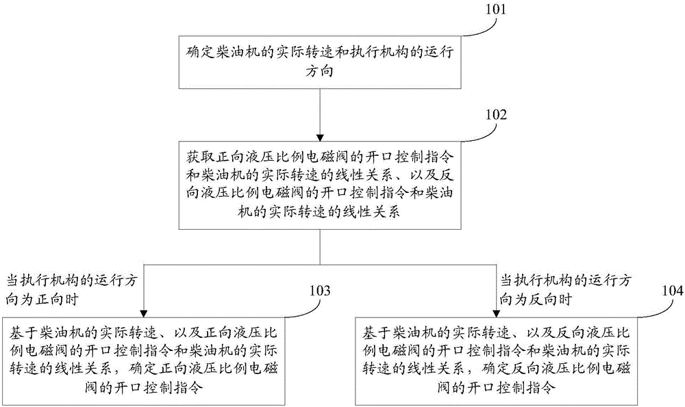
[0078] An embodiment of the present invention provides a hydraulic system control method, see figure 2 , the control method includes:

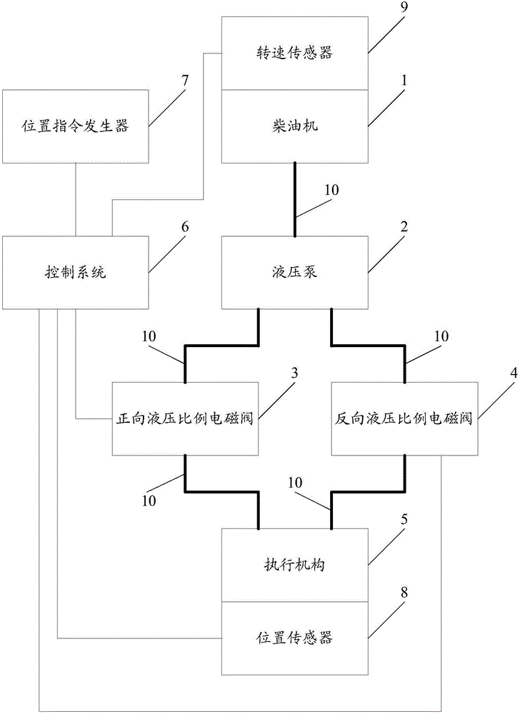
[0079] Step 101: Determine the actual rotational speed of the diesel engine and the running direction of the actuator. The running direction of the actuator includes forward and reverse.

[0080] In practical applications, when the actuator is a hydraulic cylinder, the forward direction refers to the direction in which the hydraulic oil is used to push the piston, and the reverse direction refers to the direction in which the piston moves relying on gravity or spring force; when the actuator is a hydraulic motor, the positive direction Direction refers to the direction in which the hydraulic motor rotates clockwise, and reverse refers to the direction in which the motor rotates counterclockwise.

[0081] Optionally, this step 101 may include:

[0082] Use the speed sensor to detect the actual speed of the diesel engine;

[0083] The positi...

Embodiment 2

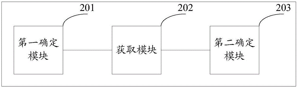
[0138] An embodiment of the present invention provides a control device for a hydraulic system, which is suitable for realizing the control method for a hydraulic system provided in Embodiment 1, see image 3 , the control unit consists of:

[0139] The first determination module 201 is used to determine the actual rotational speed of the diesel engine and the running direction of the actuator, and the running direction of the actuator includes forward and reverse;

[0140] The obtaining module 202 is used to obtain the linear relationship between the opening control command of the forward hydraulic proportional solenoid valve and the actual speed of the diesel engine, and the linear relationship between the opening control command of the reverse hydraulic proportional solenoid valve and the actual speed of the diesel engine;

[0141] The second determination module 203 is used to determine the forward hydraulic ratio based on the actual rotational speed of the diesel engine and...


PUM


Abstract

The invention discloses a method and device for controlling a hydraulic system, and belongs to the technical field of hydraulic control. The hydraulic system comprises a diesel engine, a hydraulic pump, a forward direction hydraulic proportional electromagnetic valve, a reverse direction hydraulic proportional electromagnetic valve and an executing mechanism. The control method includes the steps that the actual rotation speed of the diesel engine and the moving direction of the executing mechanism are determined, and the moving direction of the executing mechanism comprises the forward direction and reverse direction; the linear relation of an opening control instruction of the forward direction hydraulic proportional electromagnetic valve and the actual rotation speed of the diesel engine and the linear relation of an opening control instruction of the reverse direction hydraulic proportional electromagnetic valve and the actual rotation speed of the diesel engine are obtained; and when the moving direction of the executing mechanism is the forward (or reverse) direction, the opening control instruction of the forward (or reverse) direction hydraulic proportional electromagnetic valve can be determined based on the actual rotation speed of the diesel engine and the linear relation of the opening control instruction of the forward (or reverse) direction hydraulic proportional electromagnetic valve and the actual rotation speed of the diesel engine. By the adoption of the method and device, the moving speed of the executing mechanism can be kept stable.

Description

technical field [0001] The invention relates to the technical field of hydraulic control, in particular to a control method and device for a hydraulic system. Background technique [0002] In the field of industrial drive technology, the hydraulic system has the characteristics of good shock resistance, strong overload capacity and high reliability, and is widely used in various industrial occasions. [0003] The hydraulic system usually consists of a prime mover, a hydraulic pump, a control valve group (including a forward hydraulic proportional solenoid valve and a reverse hydraulic proportional solenoid valve) and an actuator. The prime mover drives the hydraulic pump to run, drives the hydraulic pump to output hydraulic oil, and the hydraulic oil flows to the actuator through the control valve group, thereby driving the actuator to run. The flow of hydraulic oil to the actuator is directly proportional to the operating speed of the actuator. [0004] In the process of ...

Claims


Application Information

Patent Timeline
Patent Type & Authority Applications(China)
IPC IPC(8): F15B9/08
CPCF15B9/08F15B2211/20523
Inventor 赵丽雄池飞飞李霞林高海涛肖源
Owner WUHAN MARINE MACHINERY PLANT
Why Eureka
Try Eureka