Pilot control valve capable of operating stably

A pilot control valve, stable technology, applied in the direction of fluid pressure actuators, servo motor components, mechanical equipment, etc., can solve the problems of restriction, main engine jitter, and large loss of flow back to the oil tank

Active Publication Date: 2016-11-16
江苏盐高阀门制造有限公司
View PDF6 Cites 4 Cited by
  • Summary
  • Abstract
  • Description
  • Claims
  • Application Information

AI Technical Summary

Problems solved by technology

The pilot control stage only has a decompression circuit composed of 2 dampers. When the control pressure at the X port fluctuates greatly due to load changes, it cannot play a good buffering role, which will cause the opening of the balance valve spool to change, causing the hydraulic cylinder to vibrate. , which can cause severe shaking of the main engine on long-arm operating equipment such as aerial work vehicles or concrete pump trucks, seriously affecting operating safety and operating accuracy
In the decompression circuit composed of the pilot control stage, a part of the oil directly flows back to the oil tank. In the large flow system, the oil return has not much influence, but in the small flow system or the pilot composed of accumulators In the handle control circuit, the flow loss of this part flowing back to the fuel tank is very large, which seriously limits the application of this invention

Method used


Image

  • Pilot control valve capable of operating stably
  • Pilot control valve capable of operating stably
  • Pilot control valve capable of operating stably

Examples


Embodiment Construction

[0019] The present invention will be further described in detail below in conjunction with the accompanying drawings and embodiments.

[0020] Such as Figure 1~3 Shown is a preferred embodiment of the present invention.

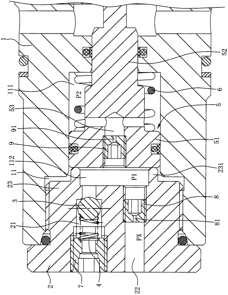
[0021] A smooth-running pilot control valve comprising

[0022] There is a valve body 1 with a piston chamber 11 inside. The front end of the valve body 1 is fixed with an end cap 2 that blocks the piston chamber 11. The end cap 2 has a threaded connection column 23 that is inserted and threaded into the piston chamber 11. The end cap 2 has a liquid outlet channel 21 and a liquid inlet channel 22 that communicate with the outside world and the piston chamber 11. The liquid outlet channel 21 communicates with the piston chamber 11 through the valve port 211. The rear end surface of the threaded column part 23 has a The annular wall 231, the annular wall 231 is used to contact with the head of the control piston 5 described below.

[0023] The first damping...


PUM


Abstract

The invention relates to a pilot control valve capable of operating stably. The pilot control valve is characterized by comprising a valve body provided with a piston cavity, a first damping hole, a one-way valve core, a control piston and a second spring, wherein an end cap is fixed at the front end of the valve body, and a liquid outlet channel and a liquid inlet channel are formed in the end cap; the first damping hole is formed in the liquid inlet channel and enables the outside to communicate with the piston cavity; the one-way valve core is arranged in the liquid outlet channel; the piston cavity is divided into a rod cavity and a rodless cavity by the head part of the control piston, a second damping hole is formed in the control piston, and a rod part of the control piston penetrates out of the top wall of the rod cavity; the second spring is arranged in the rod cavity and acts on the head part of the control piston so as to enable the control piston to keep an axial moving trend in a direction facing the end cap. The pilot control valve is reasonable in structure, and can stably control opening of a pilot valve core of a balance valve without being distributed by pressure fluctuation.

Description

technical field [0001] The invention relates to a pilot control valve, in particular to a stable pilot control valve capable of stably controlling the opening of a valve core of a hydraulic balance valve. Background technique [0002] In modern engineering machinery, construction machinery and other mechanical equipment, a large number of lifting hydraulic circuits are used. In the boom extension and retraction systems of concrete pump trucks, balance valves are usually used for hydraulic locking to ensure that the boom can be positioned at any position. Reliable stay. Among them, the balance valve is the key hydraulic component of the load control system and the hydraulic bearing system, and the performance of the balance valve directly affects the operation quality of the main engine. With the increasing difficulty of concrete pump truck operation, the requirements for sealing, self-locking, stability and multi-functionality of the balance valve are getting higher and hig...

Claims


Application Information

Patent Timeline
Patent Type & Authority Applications(China)
IPC IPC(8): F15B13/02
CPCF15B13/02F15B13/027
Inventor 陈艳艳
Owner 江苏盐高阀门制造有限公司
Why Eureka
Try Eureka