Low-emission combustion chamber for spraying oil through holes in primary combustion stage blades

A main combustion stage and combustion chamber technology, applied in combustion chambers, continuous combustion chambers, combustion methods, etc., can solve the problems of poor radial distribution uniformity of fuel oil and high emission in combustion chambers, and achieve increased residence time, enhanced blending, The effect of optimizing fuel distribution

Active Publication Date: 2016-11-16
BEIHANG UNIV
View PDF5 Cites 14 Cited by
  • Summary
  • Abstract
  • Description
  • Claims
  • Application Information

AI Technical Summary

Problems solved by technology

[0005] The purpose of the present invention is to provide a low-emission combustion chamber in which the blades of the main combustion sta

Method used


Image

  • Low-emission combustion chamber for spraying oil through holes in primary combustion stage blades
  • Low-emission combustion chamber for spraying oil through holes in primary combustion stage blades
  • Low-emission combustion chamber for spraying oil through holes in primary combustion stage blades

Examples


Embodiment Construction

[0032] The specific implementation manners of the present invention will be further described in detail below in conjunction with the accompanying drawings and embodiments. The following examples are used to illustrate the present invention, but are not intended to limit the scope of the present invention.

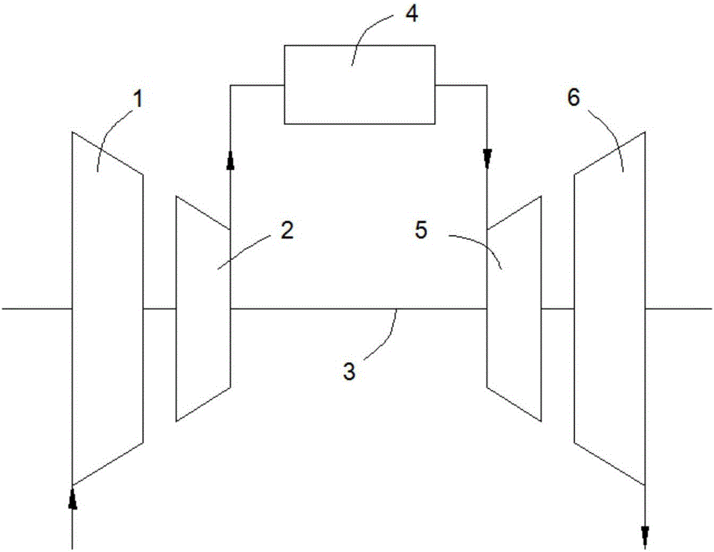
[0033] like figure 1 The schematic diagram of the engine structure shown includes a low-pressure compressor 1 , a high-pressure compressor 2 , a combustion chamber 4 , a high-pressure turbine 5 and a low-pressure turbine 6 , and the compressor and the turbine are connected to each other through a transmission shaft 3 . When the engine is working, the air is compressed by the low-pressure compressor 1 and the high-pressure compressor 2 and then enters the combustion chamber 4, where fuel is injected and combusted to form high-temperature and high-pressure gas, which impacts the high-pressure turbine 5 and the low-pressure turbine 6, thereby driving the low-pressure compress...


PUM


Abstract

The invention relates to the technical field of gas turbines, and discloses a low-emission combustion chamber for spraying oil through in primary combustion stage blades. One or more radial primary combustion stage oil through holes are formed in each primary combustion stage blade at the head of the combustion chamber. One or more primary combustion stage oil spray holes are formed in the side of each primary combustion stage blade. The primary combustion stage oil spray holes communicate with the primary combustion stage oil through holes in the corresponding primary combustion stage blades. Fuel oil enters the primary combustion stage blades along a primary combustion stage fuel oil supply circuit, a primary combustion stage oil collection chamber and the primary combustion stage oil through holes in sequence, and is sprayed out from the primary combustion stage oil spray holes to form primary combustion stage oil mist with a helical track. The primary combustion stage oil mist is mixed with air flow in a primary combustion stage channel to form an oil-air mixture, and the oil-air mixture enters a flame tube to participate in the combustion, so that blending of fuel oil and air flow is enhanced, the radial distribution uniformity of fuel oil is improved, and nitrogen oxide emission of the combustion chamber under a large working condition can be reduced remarkably; and besides, the primary combustion stage oil spray holes are far from the inner wall surface of the primary combustion stage channel, so that the condition that fuel oil is attached to the wall surface is avoided.

Description

technical field [0001] The invention relates to the technical field of gas turbines, in particular to a low-emission combustion chamber in which main combustion stage blades are opened for oil injection. Background technique [0002] There are strict restrictions on emissions of nitrogen oxides (NOx), carbon monoxide (CO), unburned hydrocarbons (UHC) and smoke (Smoke) under typical operating conditions of gas turbines. Among them, the control of nitrogen oxides is the focus of low-emission combustors. According to existing research, NOx is mainly controlled by a thermodynamic mechanism, and nitrogen in the air is oxidized at high temperature. Therefore, controlling the flame temperature in the combustion chamber is the key to reducing the amount of NOx produced. The low flame temperature affects the combustion efficiency, and at the same time, it is easy to cause excessive CO, UHC, and Smoke emissions. The study found that when the equivalence ratio of the combustion chamb...

Claims


Application Information

Patent Timeline
IPC IPC(8): F23R3/38F23R3/28
CPCF23R3/283F23R3/286F23R3/38
Inventor 林宇震韩啸王建臣张弛
Owner BEIHANG UNIV
Why Eureka
Try Eureka