A cloth drying device

A cloth drying and drying box technology, applied in the textile field, can solve the problems of uneven heating, single form, and wrinkles of the cloth, and achieve the effects of avoiding stretching deformation, preventing quality problems, and maintaining stability.

Active Publication Date: 2020-03-10
ZHEJIANG JINSHIDA ENTERPRISE
View PDF8 Cites 0 Cited by
  • Summary
  • Abstract
  • Description
  • Claims
  • Application Information

AI Technical Summary

Problems solved by technology

The existing dryer mainly includes a drying box and a heating device arranged inside the drying box. The air in the drying box is first heated by the heating device, and the temperature of the air in the drying box is reached by the heating device. After the specifications are required, the heated air is used to dry the cloth. During this process, the heating device does not directly contact the dried textile cloth, so that the drying of the cloth by the heating device needs to use air as an intermediary, so that the heating device Part of the temperature provided is used by the air when heating the air, which cannot be effectively used, making the drying efficiency low; moreover, during the long-term use of this drying method, due to the heat exchange inside the drying box, there are usually relatively large If the water vapor inside the drying box is not removed in time, it will seriously affect the drying effect of the dryer
In addition, the single type of drying device can easily cause uneven heating of the fabric, resulting in quality problems such as wrinkles that cannot be completely dried on the fabric.

Method used


Image

  • A cloth drying device
  • A cloth drying device
  • A cloth drying device

Examples


Embodiment Construction

[0031] The following are specific embodiments of the present invention combined with the accompanying drawings to further describe the technical solutions of the present invention, but the present invention is not limited to these embodiments.

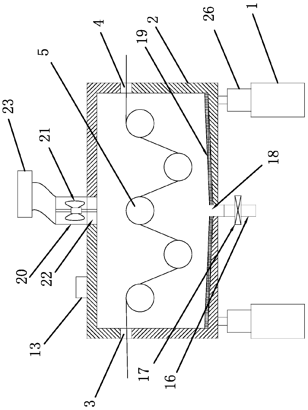
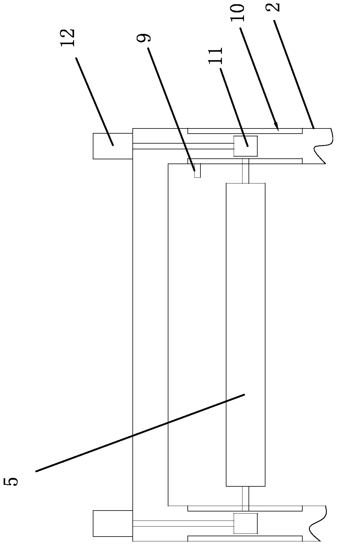
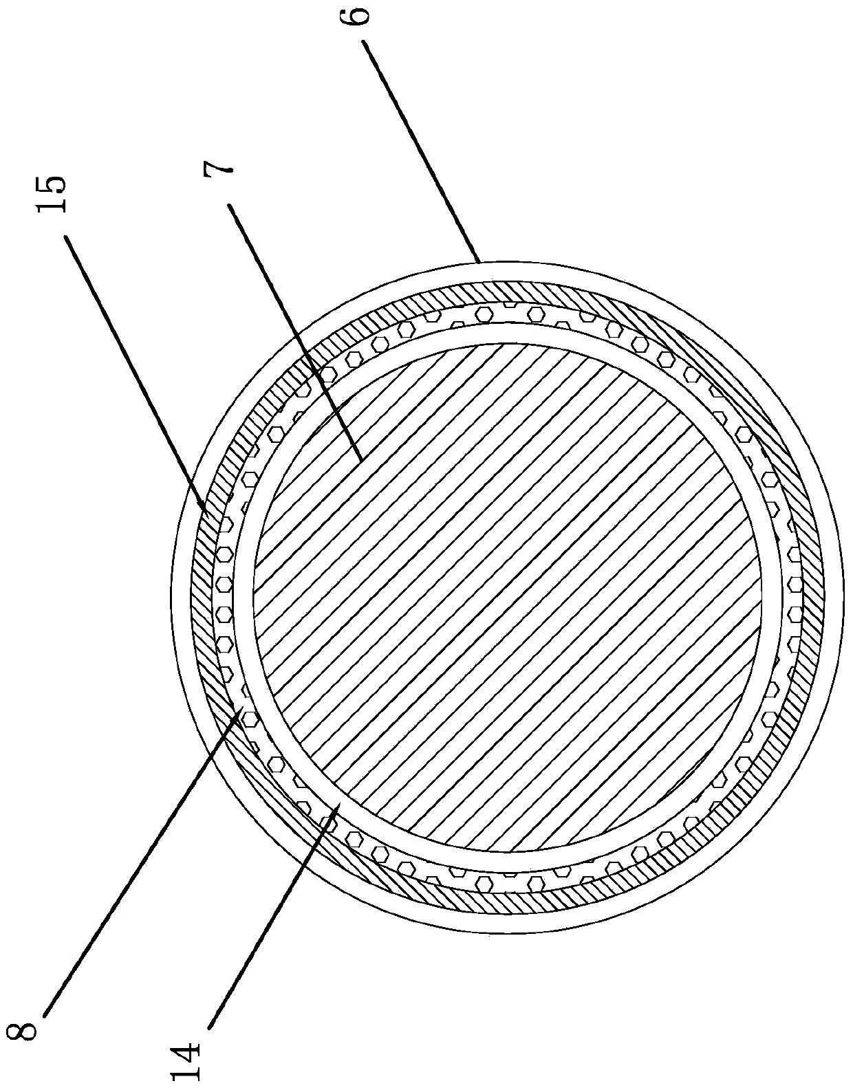
[0032] Such as figure 1 , figure 2 , image 3 , Figure 4 As shown, the cloth drying device includes a frame 1, a drying box 2 is provided at the upper end of the frame 1, and the drying box 2 is of a rectangular structure. The front and rear ends of the drying box 2 are respectively provided with a feed inlet 3 and a discharge Port 4, the drying box 2 is provided with a number of heating rollers 5, and the heating rollers 5 are arranged in parallel. The heating rollers 5 include an outer layer 6 and an inner layer 7. The outer layer 6 and the inner layer 7 form a sealed cavity and are sealed A heating system 8 is provided in the cavity.

[0033] The heating system 8 is an electric heating wire or a steam nozzle. A heat insulation layer ...


PUM


Abstract

The invention provides a cloth drying device and belongs to the technical field of textiles. The cloth drying device comprises a rack, a drying box of a rectangular structure is arranged at the upper end of the rack, and a feed inlet and a discharge outlet are formed in the front end and the rear end of the drying box correspondingly. A plurality of heating rollers are arranged in the drying box, the two ends of each heating roller are mounted on the left side wall and the right side wall of the drying box correspondingly through a connecting mechanism, and the heating rollers are arranged in parallel. A drainage system is arranged at the lower end of the drying box, and a cooling system is arranged at the upper end of the drying box. Each heating roller comprises an outer layer and an inner layer, wherein a sealed cavity is formed by the outer layer and the inner layer, and a heating system is arranged in the sealed cavity. A tension detector is further arranged in the drying box. Each connecting mechanism comprises slide rails located on the left and right sides of the drying box and T-shaped bearings directly mounted at the two ends of the corresponding heating roller. First cylinders are fixed to the upper end of the drying box, and the ends of piston rods of the first cylinders are connected with the corresponding T-shaped bearings. The cloth drying device can improve the cloth drying effect and also lower the damage rate of cloth in the drying process.

Description

Technical field [0001] The invention belongs to the technical field of textiles and relates to a cloth drying device. Background technique [0002] As we all know, the dryer is one of the indispensable production equipment in the production of textiles. The quality of the dryer will directly affect the quality of the textiles. The existing dryer mainly includes a drying box and a heating device arranged inside the drying box. The air in the drying box is heated by the heating device, and the temperature of the air in the drying box is reached by the heating device. After the specifications are required, the heated air is used to dry the fabric. In this process, the heating device does not directly contact the dried textile fabric, so that the drying of the fabric by the heating device requires air as an intermediary to make the heating device Part of the provided temperature is used by the air when heating the air, which cannot be effectively used, making the drying efficiency l...

Claims


Application Information

Patent Timeline
Patent Type & Authority Patents(China)
IPC IPC(8): F26B13/18F26B25/20F26B25/00F26B25/12F26B25/04
CPCF26B13/183F26B25/00F26B25/04F26B25/12F26B25/20
Inventor 曹煜杰
Owner ZHEJIANG JINSHIDA ENTERPRISE
Why Eureka
Try Eureka