
Waste gas heat exchanger of gas-fired boiler

A technology for gas boilers and heat exchangers, applied in indirect heat exchangers, heat exchanger types, climate sustainability, etc., and can solve problems such as heat waste

Inactive Publication Date: 2016-11-16
WUXI XINENG BOILER
View PDF8 Cites 0 Cited by
  • Summary
  • Abstract
  • Description
  • Claims
  • Application Information

AI Technical Summary

Problems solved by technology

However, the exhaust gas produced by the combustion of gas in gas-fired boilers is often directly discharged into the atmosphere, resulting in a large waste of heat.

Method used


Image

  • Waste gas heat exchanger of gas-fired boiler

Examples


Embodiment Construction

[0014] The present invention will be described in detail below in conjunction with the accompanying drawings. The description in this part is only exemplary and explanatory, and should not have any limiting effect on the protection scope of the present invention.

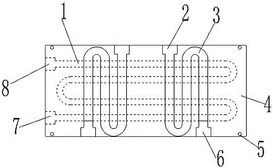
[0015] Such as figure 1 A gas boiler waste gas heat exchanger shown includes a rectangular box 4, a waste gas serpentine tube 1 and a number of coolant serpentine tubes 3,

[0016] Each single pipe of the exhaust gas serpentine pipe 1 extends along the length direction of the rectangular box 4,

[0017] A plurality of the cooling liquid serpentine pipes 3 are evenly distributed along the length direction of the rectangular box body 4 , and are in close contact with the exhaust gas serpentine pipes 1 .

[0018] The exhaust gas serpentine pipe 1 is located below each of the cooling liquid serpentine pipes 3 .

[0019] The air inlet 7 and the air outlet 8 of the exhaust gas coiled pipe 1 are located on the same side ...


PUM


Abstract

The invention discloses a waste gas heat exchanger of a gas-fired boiler. The waste gas heat exchanger of the gas-fired boiler comprises a rectangular box, a waste gas coiled pipe and a plurality of cooling liquid coiled pipes, wherein each single pipe body of the waste gas coiled pipe extends in the length direction of the rectangular box; and the cooling liquid coiled pipes are evenly distributed in the length direction of the rectangular box and tightly attached to the waste gas coiled pipe. The waste gas heat exchanger of the gas-fired boiler not only can sufficiently utilize heat in waste gas, but also is small in size and convenient to install.

Description

technical field [0001] The invention relates to the technical field of heating equipment manufacturing, in particular to a heat exchanger for waste gas of a gas boiler. Background technique [0002] At present, as the awareness of energy saving and emission reduction has generally reached a consensus among the general public, traditional pulverized coal-fired boilers have been gradually replaced by gas-fired boilers. However, the exhaust gas produced by the combustion of gas in gas-fired boilers is often directly discharged into the atmosphere, resulting in a large waste of heat. Contents of the invention [0003] Aiming at the deficiencies of the prior art, the present invention proposes a gas boiler waste gas heat exchanger, which not only can fully utilize the heat in the waste gas, but also has a small volume and is easy to install. [0004] In order to achieve the above-mentioned purpose of the invention, the present invention provides the following technical solutio...

Claims


Application Information

Patent Timeline
IPC IPC(8): F28D1/047F23J15/06
CPCF23J15/06F28D1/0477Y02E20/30
Inventor 何光伟
Owner WUXI XINENG BOILER
Features
  • Generate Ideas
  • Intellectual Property
  • Life Sciences
  • Materials
  • Tech Scout
  • Unparalleled Data Quality
  • Higher Quality Content
  • 60% Fewer Hallucinations
Learn More