
Accurate positioning and producing device for intermittent joints of similar-material rock mass samples

A technology of precise positioning and similar materials, applied in the preparation of test samples, etc., can solve problems such as theoretical analysis deviation, material waste, gap form and setting parameter differences, and achieve simple operation, exquisite design, and enhanced system stability. Effect

Active Publication Date: 2016-11-16
INST OF ROCK AND SOIL MECHANICS - CHINESE ACAD OF SCI
View PDF6 Cites 29 Cited by
  • Summary
  • Abstract
  • Description
  • Claims
  • Application Information

AI Technical Summary

Problems solved by technology

Both of the above two modes have some disadvantages: ① For the first method, the position of the steel sheet cannot be precisely positioned during the insertion process, resulting in differences between the actual crack form and the set parameters and resulting in deviations in subsequent theoretical analysis
In addition, since the insertion direction of the steel sheet is not fixed, it is very easy to cause the steel sheet to deviate from the vertical direction during the insertion process and the sample preparation fails; ②For the second method, the cracks in the first method can be solved by pre-fixing the steel sheet Uncertainty in the manufacturing process, but it limits the parameters such as the number and position of cracks. When changing the above parameters, it is often necessary to remake the entire mold, resulting in material waste

Method used


Image

  • Accurate positioning and producing device for intermittent joints of similar-material rock mass samples
  • Accurate positioning and producing device for intermittent joints of similar-material rock mass samples
  • Accurate positioning and producing device for intermittent joints of similar-material rock mass samples

Examples


Embodiment 1

[0024] The present invention will be described in further detail below in conjunction with the accompanying drawings.

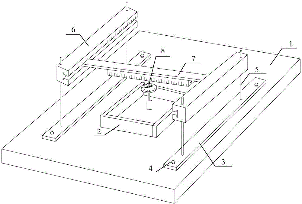
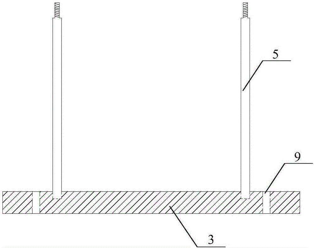
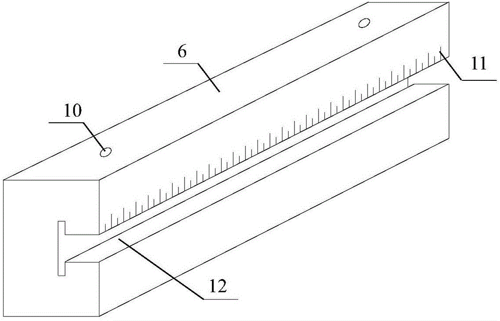
[0025] The invention relates to a device for precisely positioning intermittent joints of similar material rock mass samples. It consists of a sample preparation base plate 1, a sample mold 2, a fissure positioning support base plate 3, a fissure positioning support anchor bolt 4, a fissure positioning support rod 5, a fissure longitudinal positioning rod 6, a fissure transverse positioning rod 7, a fissure angle positioning device 8, and a fissure positioning rod. Positioning bracket anchor hole 9, crack longitudinal positioning rod anchor hole 10, crack longitudinal positioning scale 11, T-shaped through groove 12, lateral positioning rod slider 13, crack angle positioning chute 14, crack angle positioning slider 15, angle pointer 16. Angle dial 17, telescopic rod 18, steel sheet 19, and angle scale 20 form. Such as figure 1As shown, the connection relati...


PUM


Abstract

The invention discloses a device for accurately positioning intermittent joints of similar material rock mass samples. The bottom plate of the crack positioning bracket is arranged in parallel on both sides of the sample mold, and the anchor bolts of the crack positioning bracket are anchored on the sample preparation base plate. The crack positioning bracket It is connected with the bottom plate of the crack positioning bracket through threads, and the crack longitudinal positioning rods are respectively arranged parallel to the crack positioning bracket bottom plate and fixed on the four crack positioning brackets by screws. The slider of the horizontal positioning rod is stuck in the groove of the longitudinal positioning rod of the crack, and the angle positioning device is stuck in the groove at the lower end of the horizontal positioning rod of the crack through the square slider at the top, and the crack is made by the steel plate at the lower end of the angle positioning device. The structure is simple and the operation is convenient, which effectively guarantees the high-efficiency creation of fractures and the enrichment of fracture forms, which greatly facilitates the strength and deformation behavior tests of rock masses with different fractures, and quickly creates intermittent fractures with specified parameters.

Description

technical field [0001] The invention relates to the technical field of model testing of rock mass similar materials, and more specifically relates to a crack making device capable of adjusting geometric parameters such as the position, quantity, angle, length and opening of intermittent cracks of similar material rock mass and accurately positioning the parameters. It is suitable for the precise positioning and fabrication of intermittent joints of different numbers and geometric forms in rock mass samples of similar materials. Background technique [0002] Cracks such as faults and joints in natural rock mass have a great influence on the mechanical properties and engineering stability of rock mass. On the one hand, the deformation and failure process of rock mass is essentially the process of initiation, expansion, interaction and penetration of cracks under engineering disturbance conditions. On the other hand, the complex crack forms existing in rock mass change the rock...

Claims


Application Information

Patent Timeline
IPC IPC(8): G01N1/28G01N1/36
CPCG01N1/28G01N1/36
Inventor 刘学伟刘泉声何军刘建平魏莱雷广峰
Owner INST OF ROCK AND SOIL MECHANICS - CHINESE ACAD OF SCI
Learn More