Driving circuit of liquid crystal display panel and liquid crystal display panel using same

A liquid crystal display panel and driving circuit technology, which is applied to static indicators, identification devices, instruments, etc., can solve the problems of large difference in brightness, enlarged display brightness of liquid crystal display panels, and inability to use GOA technology for liquid crystal display panel driving. Uniform display and better picture quality

Inactive Publication Date: 2016-11-16
TCL CHINA STAR OPTOELECTRONICS TECH CO LTD
View PDF7 Cites 13 Cited by
  • Summary
  • Abstract
  • Description
  • Claims
  • Application Information

AI Technical Summary

Problems solved by technology

[0007] The purpose of the present invention is to provide a driving circuit and a liquid crystal display of a liquid crystal display panel, to solve the problem in the prior art that the liquid crystal display panel is enlarged from top to bottom due to the input signal driving the GOA work through a relatively large impedance. The difference in display brightness from top to bottom, even due to the large difference in brightness, the problem that the LCD panel driver cannot use GOA technology

Method used


Image

  • Driving circuit of liquid crystal display panel and liquid crystal display panel using same
  • Driving circuit of liquid crystal display panel and liquid crystal display panel using same
  • Driving circuit of liquid crystal display panel and liquid crystal display panel using same

Examples


Embodiment 1

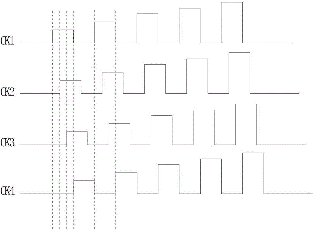
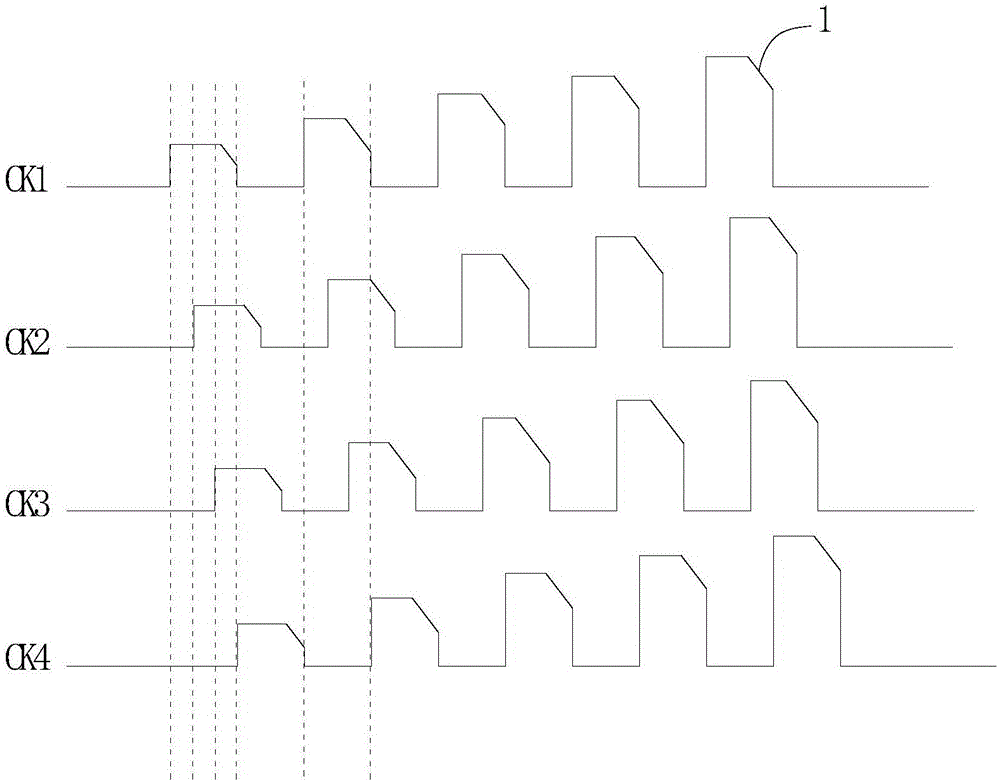
[0031] Please refer to figure 1 with figure 2 , figure 1 It is a schematic diagram of the waveform shape of the set waveform in this embodiment, figure 2 It is a schematic diagram of the waveform shape of the set waveform of the waveform with chamfered angle 1 in this embodiment. from figure 1 with figure 2 can be seen:

[0032] A driving circuit of a liquid crystal display panel of the present invention is used to output a plurality of clock control signals to drive the scanning lines of the display area of ​​the liquid crystal display panel row by row after passing through the GOA circuit of the liquid crystal display panel. The clock control signal of the setting waveform, wherein the setting waveform is a periodic square wave shape, the high potential of the setting waveform increases periodically, and the time length of each cycle of the setting waveform is the same .

[0033] Wherein, the number of the clock control signal can be multiple, and the present em...

Embodiment 2

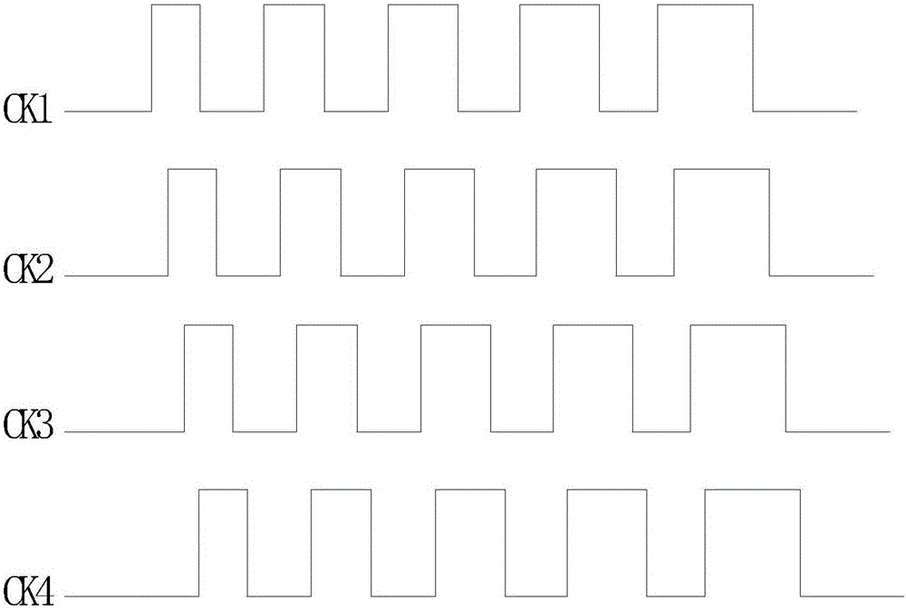
[0038] Please refer to image 3 with Figure 4 , image 3 It is a schematic diagram of the waveform shape of the set waveform in this embodiment, Figure 4 It is a schematic diagram of the waveform shape of the set waveform with chamfered waveform 2 in this embodiment. from image 3 with Figure 4 can be seen:

[0039] A driving circuit of a liquid crystal display panel of the present invention is used to output a plurality of clock control signals to drive the scanning lines of the display area of ​​the liquid crystal display panel row by row after passing through the GOA circuit of the liquid crystal display panel. Set the clock control signal of the waveform, wherein the set waveform is a periodic square wave shape, the high potential waveform width of the set waveform increases periodically, and the time length of each cycle of the set waveform is the same .

[0040] Wherein, the number of the clock control signal can be multiple, and the present embodiment is prefe...

Embodiment 3

[0045] Please refer to Figure 5 with Image 6 , Figure 5 It is a schematic diagram of the waveform shape of the set waveform in this embodiment, Image 6 It is a schematic diagram of the waveform shape of the set waveform of the waveform with chamfered angle 3 in this embodiment. from Figure 5 with Image 6 can be seen:

[0046] A driving circuit of a liquid crystal display panel of the present invention is used to output a plurality of clock control signals to drive the scanning lines of the display area of ​​the liquid crystal display panel row by row after passing through the GOA circuit of the liquid crystal display panel. Set the clock control signal of the waveform, wherein the set waveform is a periodic square wave shape, the high potential of the set waveform and the width of the high potential waveform increase periodically, and each period of the set waveform The length of time is the same.

[0047] Wherein, the number of the clock control signal can be mul...


PUM


Abstract

The invention provides a driving circuit of a liquid crystal display panel and a liquid crystal display panel using same. The driving circuit is used for outputting a plurality of clock control signals for driving scanning lines of the display area of the liquid crystal display panel in a one-to-one manner after passing through the GOA circuit of the liquid crystal display panel. The driving circuit and the liquid crystal display panel are characterized in that the driving circuit uses the clock control signals with preset waveforms, wherein the preset waveforms are periodical square waves; the high levels of the preset waveforms periodically increase; and furthermore the time lengths of the periods of the preset waveforms are same. The driving circuit and the liquid crystal display panel have advantages of reducing brightness differences in the vertical direction and the left-and-right direction of the liquid crystal display panel, improving driving capability of the GOA circuit, realizing higher display brightness uniformity of a large-dimension high-resolution liquid crystal display panel, and obtaining higher definition of a displayed picture.

Description

【Technical field】 [0001] The invention relates to the field of liquid crystal display, in particular to a driving circuit of a liquid crystal display panel and a liquid crystal display panel. 【Background technique】 [0002] Liquid crystal display (Liquid Crystal Display, LCD) and other flat display devices are widely used in mobile phones, televisions, personal digital assistants, digital cameras, notebooks, etc. Various consumer electronic products such as computers and desktop computers have become the mainstream of display devices. Most of the liquid crystal display devices currently on the market are backlight liquid crystal displays, which include a liquid crystal display panel (TFT-LCD) and a backlight module. The working principle of the liquid crystal display panel is to place liquid crystal molecules between two parallel glass substrates. There are many vertical and horizontal small wires between the two glass substrates. The direction of the liquid crystal molecul...

Claims


Application Information

Patent Timeline
Patent Type & Authority Applications(China)
IPC IPC(8): G09G3/36
CPCG09G3/3677G09G2300/0408G09G2310/08G09G2320/0223G09F9/35G09G3/2011G09G3/36G09G3/3614G09G3/3648G09G2310/0289
Inventor 李文英
Owner TCL CHINA STAR OPTOELECTRONICS TECH CO LTD
Why Eureka
Try Eureka