
Novel gyrotron traveling wave tube input coupler

An input coupling, traveling wave tube technology, applied in the field of new gyroscopic traveling wave tube input couplers, can solve the problems of inability to meet the requirements of broadband, high-end reflection, low transmission rate, etc., to reduce reflected waves, reduce bandwidth, Realize the effect of working frequency band

Active Publication Date: 2016-11-16
UNIV OF ELECTRONICS SCI & TECH OF CHINA
View PDF3 Cites 4 Cited by
  • Summary
  • Abstract
  • Description
  • Claims
  • Application Information

AI Technical Summary

Problems solved by technology

However, this structure usually has a large reflection at the high end of the frequency band and a low transmission rate, resulting in a narrow bandwidth
Can not meet the requirements of broadband

Method used


Image

  • Novel gyrotron traveling wave tube input coupler
  • Novel gyrotron traveling wave tube input coupler
  • Novel gyrotron traveling wave tube input coupler

Examples


Embodiment Construction

[0015] Below in conjunction with design example and accompanying drawing, the present invention will be described in further detail.

[0016] This embodiment provides a convoluted traveling wave tube input coupler working in the Ku band and TE01 mode, and its technical specification requirements are as follows:

[0017] Main waveguide working mode: circular waveguide TE01 mode.

[0018] Input signal mode: rectangular waveguide TE10 mode.

[0019] Working frequency band: Ku band, namely 12.4GHz-18GHz.

[0020] Standard rectangular waveguide model: BJ180, wide side size 12.954 mm, narrow side size: 6.477 mm.

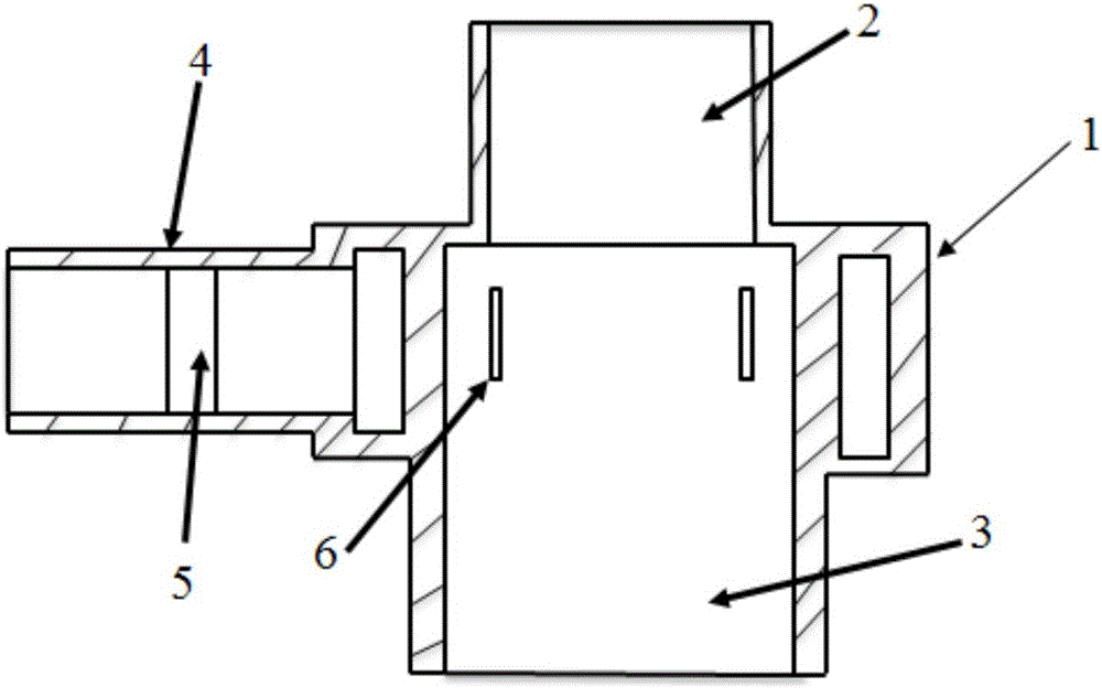
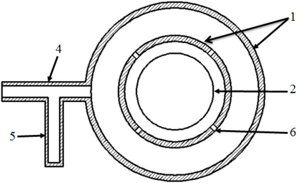
[0021] The structure of the input coupler of the convoluted traveling wave tube provided by this embodiment is as follows: figure 1 , figure 2 As shown, the main structure and specific dimensions are as follows: 1 is a coaxial cavity structure, the inner radius of the inner conductor is 12.3mm, the thickness is 0.5mm, the inner radius of the outer conductor is 16mm, ...


PUM


Abstract

The invention discloses a novel gyrotron traveling wave tube input coupler, and belongs to the technical field of microwave and millimeter-wave devices. The novel gyrotron traveling wave tube input coupler comprises a coaxial structure, a cut-off circular waveguide, an output circular waveguide and a rectangular input waveguide, wherein the cut-off circular waveguide and the output circular waveguide are arranged at two ends of the coaxial structure respectively; the rectangular input waveguide is arranged on the side surface of the coaxial structure; a plurality of coupling gaps are arranged in an inner conductor of the coaxial structure; and a short-circuit branch rectangular waveguide is arranged on an E surface of the rectangular input waveguide. The short-circuit branch waveguide is arranged on the E surface of the rectangular input waveguide on the basis of a traditional gyrotron traveling wave tube. Reflection of the input coupler can be effectively offset by reasonably designing the position and structure parameters of the short-circuit branch waveguide; and the transmission efficiency of a high-frequency end is improved, so that the input bandwidth is effectively expanded.

Description

technical field [0001] The invention belongs to the technical field of microwave and millimeter wave devices, and in particular relates to a novel gyrotron traveling wave tube input coupler and a design method thereof. Background technique [0002] In the cyclotron traveling wave tube, the input electromagnetic wave interacts with the electrons in spiral motion. At this time, due to the influence of the relativistic negative mass effect, the electron beams form angular clusters in the lateral direction, and continue to spiral forward to reach the high-frequency interaction. The area of ​​effect falls into the deceleration field. In the high-frequency deceleration field, part of the energy of the electron injection is converted to the high-frequency field to realize the amplification of the high-frequency field, so that high-power microwaves and millimeter waves are obtained at the output end. [0003] The cyclotron traveling wave tube input coupler is a coupling input devic...

Claims


Application Information

Patent Timeline
Patent Type & Authority Applications(China)
IPC IPC(8): H01J23/36H01J25/34
CPCH01J23/36H01J25/34
Inventor 王建勋任绪迅夏建波罗勇
Owner UNIV OF ELECTRONICS SCI & TECH OF CHINA
Learn More