Organic electroluminescent device

An electroluminescent device and luminescence technology, which is applied in the direction of organic semiconductor devices, electric solid state devices, electrical components, etc., can solve the problems of large viewing angle brightness drop, large viewing angle deviation, etc.

Active Publication Date: 2016-11-16
BOE TECH GRP CO LTD
View PDF9 Cites 23 Cited by
  • Summary
  • Abstract
  • Description
  • Claims
  • Application Information

AI Technical Summary

Problems solved by technology

[0004] The invention provides an organic electroluminescent device, which solves the technical problems of the decrease in the brightness of the organic ...

Method used


Image

  • Organic electroluminescent device
  • Organic electroluminescent device
  • Organic electroluminescent device

Examples


Embodiment Construction

[0036] The following will clearly and completely describe the technical solutions in the embodiments of the present invention with reference to the accompanying drawings in the embodiments of the present invention. Obviously, the described embodiments are only some, not all, embodiments of the present invention. Based on the embodiments of the present invention, all other embodiments obtained by persons of ordinary skill in the art without making creative efforts belong to the protection scope of the present invention.

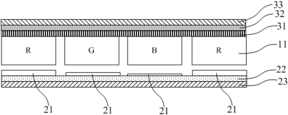
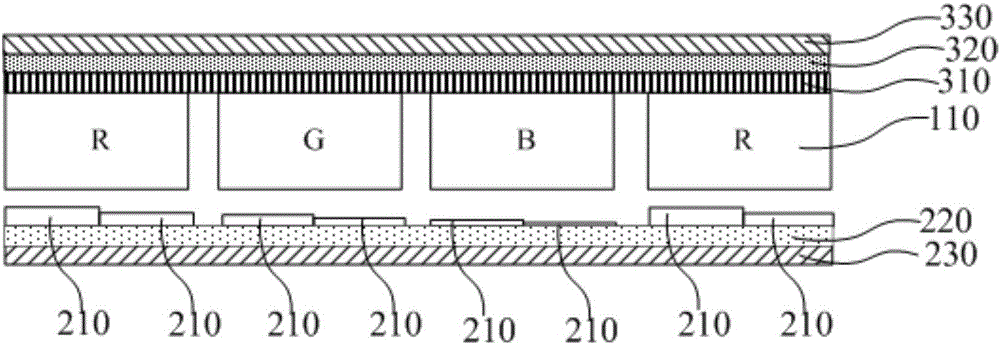
[0037] The organic electroluminescent device of an embodiment of the present invention, such as figure 2 , image 3 and Figure 4 shown, including:

[0038] The light-emitting layer includes a plurality of light-emitting regions 110 arranged in an array, the light-emitting regions 110 are organic electroluminescent regions, and the colors of the light-emitting regions can include red, green and blue, represented by R, G, and B respectively;

[0039] A hole...


PUM


Abstract

The invention discloses an organic electroluminescent device, and the device comprises a light-emitting layer which comprises a plurality of light-emitting regions arranged in an array, wherein the light-emitting regions are organic electroluminescent regions; a hole transmission layer, an anode and a reflecting layer, which are sequentially arranged from the light-emitting layer to a light outgoing side far from the organic electroluminescent device; an electronic transmission layer, a cathode and a semi-transmitting and semi-reflecting layer, which are sequentially arranged from the light-emitting layer to a light outgoing side close to the organic electroluminescent device. The projection of each light-emitting region on the hole transmission layer serves as the first position, and the thicknesses of the hole transmission layer at at least one first position at least comprise two preset thicknesses. Compared with the prior art, the device solves a technical problem that a micro-cavity structure causes the decrease of the big-view-angle brightness of the device and the big-view-angle color cast.

Description

technical field [0001] The invention relates to the field of organic electroluminescence, in particular to an organic electroluminescence device. Background technique [0002] Organic electroluminescent devices with microcavity structures in the prior art, such as figure 1 As shown, it includes a light-emitting layer, wherein the light-emitting layer includes a plurality of light-emitting regions 11 arranged in an array, the light-emitting regions are organic electroluminescent regions, and the colors of the light-emitting regions can include red, green and blue, respectively R, G, B represents; The hole transport layer that one side of self-luminous layer is arranged successively, anode 22 and reflection layer 23; The electron transport layer 31 that the other side of self-luminous layer is arranged successively, negative electrode 32 and semi-transparent semi-reflective layer 33; Empty A hole transport region 21 of preset thickness is provided in the hole transport layer ...

Claims


Application Information

Patent Timeline
IPC IPC(8): H01L51/50
CPCH10K50/15H10K50/852H10K59/35H10K2102/3026H10K2102/351H10K50/156H10K50/125
Inventor 樊星闫光
Owner BOE TECH GRP CO LTD
Why Eureka
Try Eureka