Phase shifting assembly, phase shifting device and phase shifting system

A phase shifter and phase shift technology, which is applied to electrical components, waveguide devices, antennas, etc., can solve the problems of the movable transmission line without wear-resistant insulating layer, the lack of structural layout space, and the length of the phase shifter. The effect of reducing interference sources, simple structure and improving stability

Inactive Publication Date: 2016-11-16
COMBA TELECOM TECH (GUANGZHOU) CO LTD
View PDF7 Cites 2 Cited by
  • Summary
  • Abstract
  • Description
  • Claims
  • Application Information

AI Technical Summary

Problems solved by technology

[0005] Among them, one of the disadvantages of the above-mentioned existing phase shifter is that the stroke of the phase shifter is outside the cavity of the phase shifter, so that the length of the entire phase shifter becomes longer, and the effect of miniaturization cannot be achieved.
[0006] The second disadvantage of the above-mentioned existing phase shifter is that there is no wear-resistant insulating layer on the movable transmission line, and in repeated use, it may cause poor contact and cause passive intermodulation products
[0007] The third disadvantage of the above-mentioned existing phase shifter is that when the phase shifter is applied to a base station antenna that can be continuously electrically downtilted, an additional power divider is required to connect the layout and form a network. In this way, when a multi-unit array is formed , the structural layout space is seriously insufficient
[0008] The fourth shortcoming of the above-mentioned existing phase shifter is: use stroke limiting components (for example, spring structure) to limit the left and right movement stroke of the transmission line and ensure that the phase shifter will not be damaged when the transmission line moves left and right. source intermodulation products

Method used


Image

  • Phase shifting assembly, phase shifting device and phase shifting system
  • Phase shifting assembly, phase shifting device and phase shifting system
  • Phase shifting assembly, phase shifting device and phase shifting system

Examples


Embodiment Construction

[0036] The present invention will be further described below with reference to the accompanying drawings and exemplary embodiments, wherein the same reference numerals in the accompanying drawings all refer to the same components. Also, detailed descriptions of known arts will be omitted if they are unnecessary to illustrate the features of the present invention.

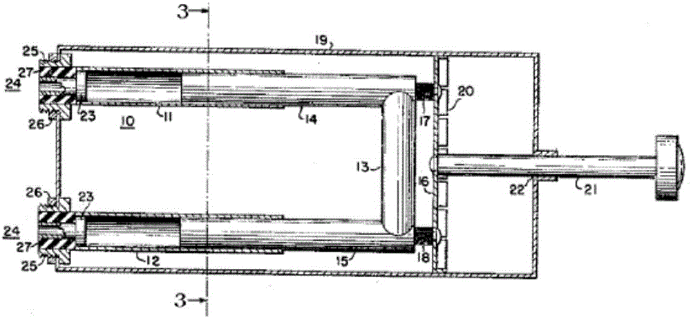
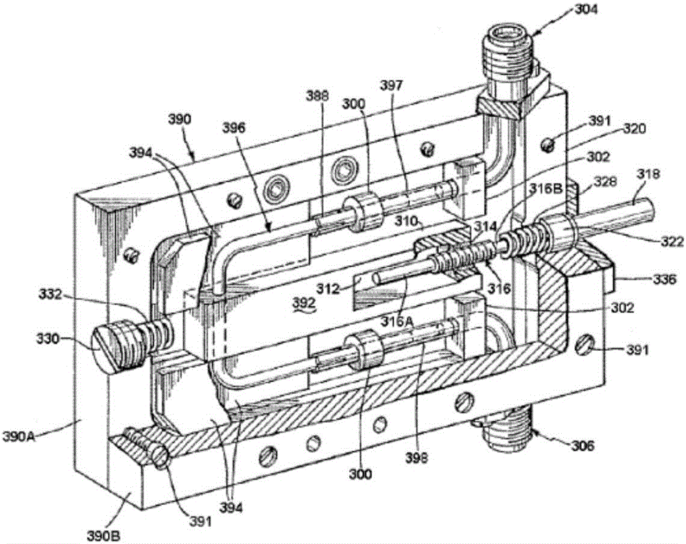
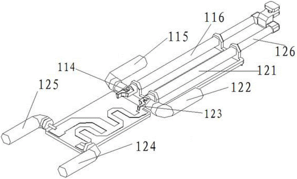
[0037] Please see attached Figure 3-6, which together disclose a typical embodiment of the phase shifter of the present invention. The phase shifting assembly in the phase shifter of the present invention includes an outer conductor and an inner conductor that are coaxially sleeved, and the outer conductor or the inner conductor is fixed with a The transmission block 117 that produces relative displacement, the moving path of the transmission block 117 is set in a preset area, so that when the phase shifting assembly is installed in the cavity 111, the cavity 111 does not need to be in the axial direction The acc...


PUM


Abstract

The invention relates to the technical field of communication antennas and in particular relates to a phase shifting assembly, a phase shifting device and a phase shifting system. The phase shifting assembly is used for adjusting a phase of a signal flowing through the phase shifting assembly and comprises an outer conductor and an inner conductor, which are coaxially arranged in a sleeving manner, wherein the outer conductor or the inner conductor is fixedly provided with a transmission block for conveniently controlling the outer conductor or the inner conductor to have relative displacement along the axial direction; and a movable path of the transmission block is set in a pre-set range, so that a containing space for containing the transmission block does not need to be designed on the cavity in the axial direction and the transmission block does not extend out of the cavity in the axial direction when the phase shifting assembly is mounted in the cavity. The phase shifting device provided by the invention has the advantages of miniaturization, simple structure, relatively low cost, relatively good passive intermodulation, convenience for structure layout, relatively low loss and relatively stable properties in all aspects; and meanwhile, related data indexes including shaping, gain and the like can be conveniently improved, so that the transmission and emission of ultra-wideband signals can be conveniently realized.

Description

【Technical field】 [0001] The present invention relates to the technical field of communication antennas, in particular to related technologies related to phase shifting related devices in communication antenna technology, and in particular to a phase shifting component, a phase shifter and a phase shifting system. 【Background technique】 [0002] With the development of mobile communications, more and more users have become aware of electromagnetic radiation, and began to have a fear of electromagnetic radiation, worrying that radiation will affect their health, which makes it difficult for communication operators to choose a site to build a site. The cost increases, which in turn forces the location of the station to be selected in a place with a more complex geographical environment and geomagnetic environment; as the surrounding geographical and electromagnetic environment becomes increasingly complex, its requirements for communication antennas will also become higher and ...

Claims


Application Information

Patent Timeline
IPC IPC(8): H01P1/18H01Q3/30
CPCH01P1/18H01Q3/30
Inventor 陶世强胡成才黄明达刘聪
Owner COMBA TELECOM TECH (GUANGZHOU) CO LTD
Why Eureka
Try Eureka