

Box-type guide rail portable satellite communication antenna
A satellite communication, box-type technology, applied in the field of satellite communication, can solve the problems of heavy weight, high precision transmission gear, and strict manufacturing process requirements, and achieve the effect of reducing weight and ensuring accuracy
- Summary
- Abstract
- Description
- Claims
- Application Information
AI Technical Summary
Problems solved by technology
Method used
Image

Examples
Embodiment 1
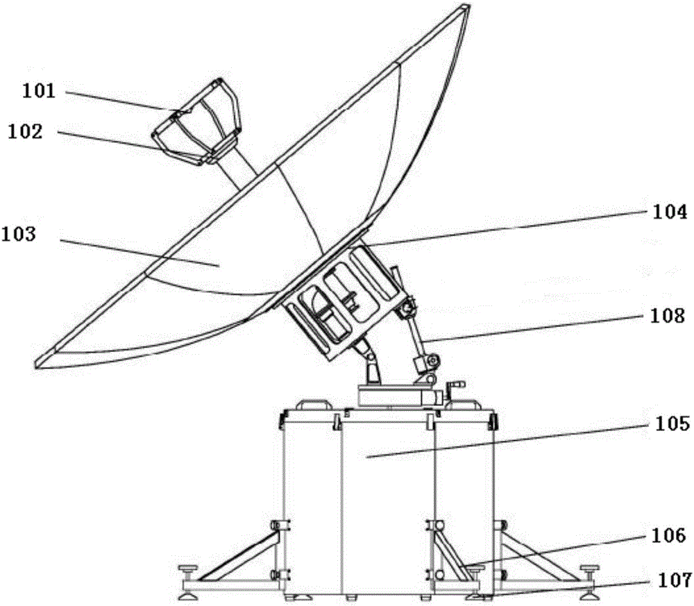
[0048]Such as Figure 1-Figure 7 As shown, the box-type guide rail portable satellite communication antenna of the present invention includes an antenna communication assembly, a box support assembly, a guide rail base 201 and a drive assembly. The drive assembly is used to provide power for the support assembly to adjust the horizontal rotation and pitch angle. Meanwhile, the box support assembly is located at the bottom of the antenna communication assembly, and the bottom end is slidably connected to the guide rail base 201 . The drive assembly is fixed on the box support assembly. Specifically, the drive assembly may be located inside the box support assembly, or on the upper surface of the box support assembly, or on the The end face of the box support assembly.
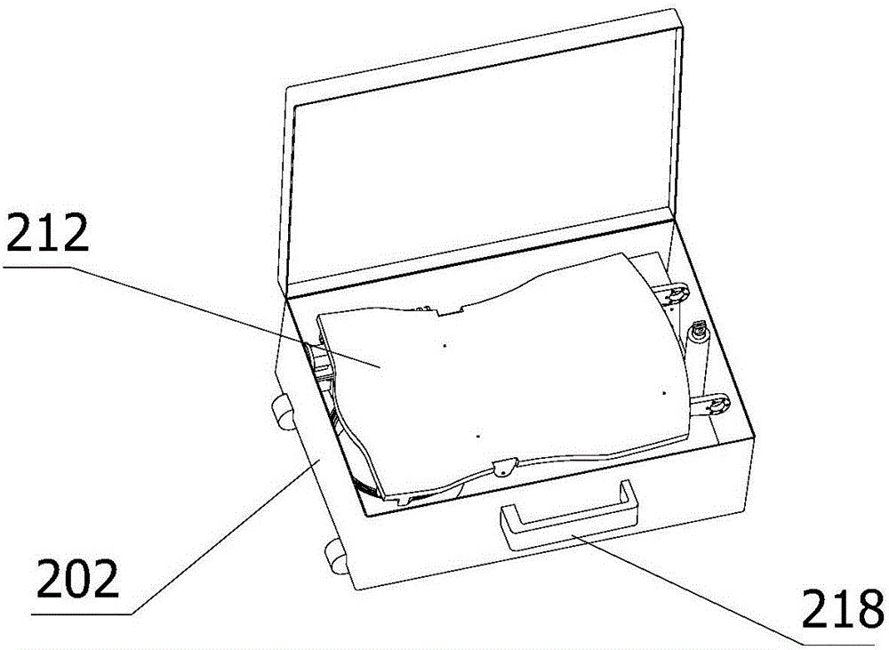
[0049] Wherein, the box supporting assembly includes a packing box 202, a pitch support component 203 and a pitch driving mechanism 204; the packing box 202 is provided with a pull rod 217 and a handle 218 on ...
Embodiment 2
[0059] Such as Figure 9 As shown, it differs from Embodiment 1 only in that it adopts a manual adjustment mode, that is, there are changes in the driving components and a human-computer interaction interface 216 . The driving assembly specifically includes a load-bearing wheel 208, a second limiting wheel 210 and a locking position 215; the load-bearing wheel 208 is located at the end of the second limiting wheel 210, and is used to carry the weight of the communication antenna assembly; the second The limiting wheel 210 is located on one side of the guide rail base 201, and is engaged with the strip groove 206 (a); the first limiting wheel 205 is located on the other side of the guide rail base 201, and is used to limit the driving assembly on the guide rail base. 201 slides in the bar-shaped groove 206 (a), and the locking position 215 is located on one side of the second limiting wheel 210, which is used to lock the second limiting wheel 210 after star alignment, so that t...
Embodiment 3
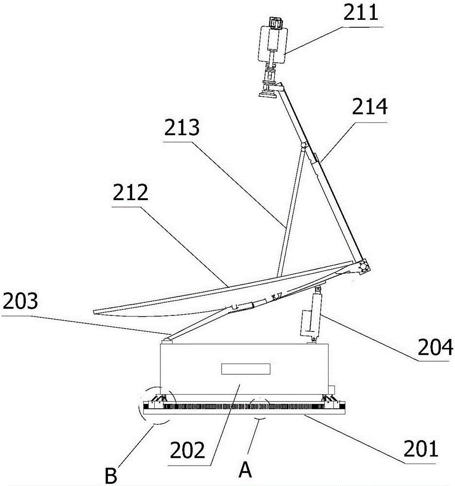
[0063] Such as Figure 11 As shown, the difference between this embodiment and Embodiment 1 is that: the antenna reflective surface 212 adopts the mode of forward installation, and the mode of reverse installation is adopted in Embodiments 1 and 2. Specifically, it can be combined with Embodiment 1 middle image 3 and Figure 4 Compare.
[0064] For the forward or reverse installation of the antenna reflective surface 212, there are two different usage methods. Specifically, both have the same antenna gain and the same ability to receive signals; the difference is that the antenna reflective surface 212 installed in the forward direction is used in an environment with a wide front view. The antenna reflecting surface 212 can make the antenna receiving surface free of dust and snow accumulation; the antenna reflecting surface 212 installed in the reverse direction is suitable for an open environment above the receiving surface, can save space, and has better wind resistance ...
PUM
 Abstract
Description
Claims
Application Information