CAN bus connector of controller module

A CAN bus and controller module technology, applied in the field of automation control, can solve the problems of procurement, transportation, installation trouble, reliability reduction, complicated installation process, etc., to achieve the effect of reducing production and processing steps, reducing production links, and connecting firmly

Inactive Publication Date: 2016-11-16
杭州新湾科技有限公司
View PDF8 Cites 1 Cited by
  • Summary
  • Abstract
  • Description
  • Claims
  • Application Information

AI Technical Summary

Problems solved by technology

[0003] There are some defects in the use of the above two bus connectors: 1. The equipment base connector, the base connector forms a bus base through multiple serial connections, and the equipment module is connected to the bus base again to form multiple insertions, which is reliable The performance is reduced; in some occasions with vibration, the connection is often dropped
Since the base connector is an independent component, it needs to be equipped separately, which will cause more troubles in procurement, transportation and installation
2. Jumper connector, the jumper connector usually adopts the method of adding male and female connectors at both ends of the data cable. This connection method is generally used for the connection of the CAN bus. When used in the automation control system, the connection method of the jumper is used , will use smaller connectors, because the module connection uses jumper wires, the system connection lines are particularly large, resulting in reduced reliability and complicated installation process
[0005] The above solution uses metal shrapnel for line shielding, which is simple in design, fast in production, and convenient in installation, but it still does not solve the technical problem of fast and reliable connection of two CAN bus connectors

Method used


Image

  • CAN bus connector of controller module
  • CAN bus connector of controller module
  • CAN bus connector of controller module

Examples


Embodiment Construction

[0022] The present invention will be described in further detail below in conjunction with the accompanying drawings and specific embodiments.

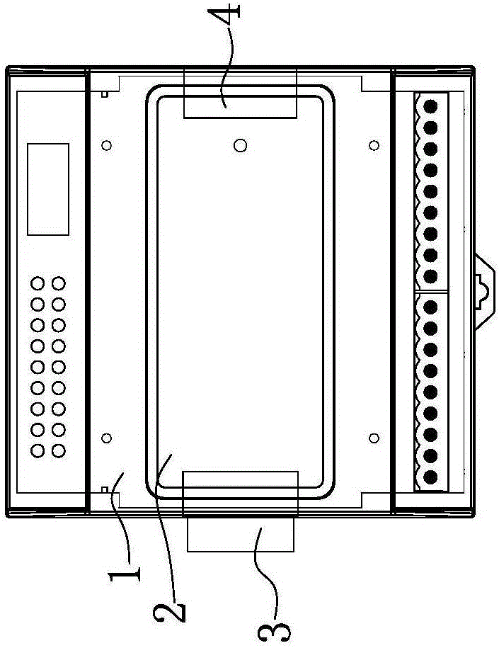
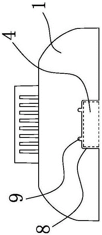
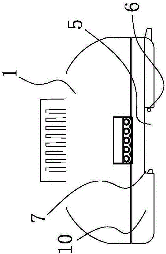
[0023] like figure 1 and image 3 As shown, a CAN bus connector of a controller module includes a housing 1, a module circuit board 2 is arranged inside the housing, and a male connector 3 and a female connector 3 are respectively connected to both sides of the module circuit board 2. Connector 4, the male connector 3 extends out of the housing 1, and the female connector 4 is located inside the housing 1. Those skilled in the art should understand that the end of the female connector 4 can be flush with the side of the housing 1, or It may be a recess and a side wall of the housing 1 . like Figure 4 As shown, the male connector 3 is compatible with the female connector 4 and when the two CAN bus connectors are close to each other, the male connector 3 on one CAN bus connector can be inserted into the female connector 4 on the oth...


PUM


Abstract

The invention belongs to the technical field of automatic control and relates to a CAN bus connector of a controller module. The CAN bus connector comprises a housing. The housing is internally provided with a module circuit board. The two sides of the module circuit board are connected with a male connector and a female connector respectively. The male connector extends out of the housing; the female connector is arranged in the housing; and the male connector and the female connector are matched, and when two CAN bus connectors draw near to each other, the male connector of one CAN bus connector can be inserted to the female connector of the other female connector to enable the two CAN bus connectors to realize electric connection. The CAN bus connector is reliable and quick to connect and high in stability.

Description

technical field [0001] The invention belongs to the technical field of automation control and relates to a CAN bus connector of a controller module. Background technique [0002] Among automation control system products, CAN bus is a field bus commonly used in automation control systems in recent years. There are two types of CAN bus connectors commonly used in the market: 1. Device base bus connector, 2. Device jumper connection bus connector. [0003] There are some defects in the use of the above two bus connectors: 1. The equipment base connector, the base connector forms a bus base through multiple serial connections, and the equipment module is connected to the bus base again to form multiple insertions, which is reliable The performance is reduced; in some occasions with vibration, the connection is often dropped. Since the base connector is an independent component, it needs to be equipped separately, which causes more troubles in procurement, transportation, and i...

Claims


Application Information

Patent Timeline
Patent Type & Authority Applications(China)
IPC IPC(8): H01R13/405H01R13/627H01R13/66
CPCH01R13/405H01R13/627H01R13/665
Inventor 冯华强
Owner 杭州新湾科技有限公司
Why Eureka
Try Eureka