Electric connection method for secondary arc prevention

A secondary arc and electrical connection technology, applied in the direction of conductive adhesive connection, contact parts, base/housing, etc., can solve the problems of low service life, damage to electrical contact ends, etc., and achieve separation or falling off, good promotion, design simple effects

Inactive Publication Date: 2016-11-16
ARGANGLE TECH
View PDF6 Cites 0 Cited by
  • Summary
  • Abstract
  • Description
  • Claims
  • Application Information

AI Technical Summary

Problems solved by technology

Because the secondary arc is often generated between the gaps between the two electrical connections, it is easy to be ignored by people, but the secondary arc often causes damage to the electrical contacts, resulting in a lower service life of the equipment

Method used


Image

  • Electric connection method for secondary arc prevention
  • Electric connection method for secondary arc prevention
  • Electric connection method for secondary arc prevention

Examples


Embodiment 1

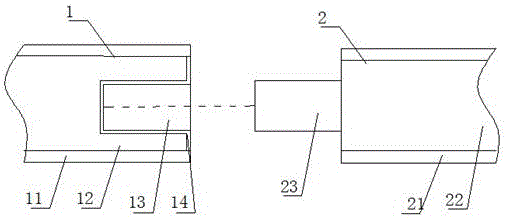
[0027] Such as figure 1 As shown, the electrical connector for preventing secondary arc of the present invention includes a first connecting end 1 and a second connecting end 2 .

[0028] The first connection end 1 includes a first insulating layer 11 and a first conductor 12. The first insulating layer 11 is wrapped around the outside of the first conductor 12. The connection side of the first conductor 12 is provided with a connection groove 13, which has a fluid conductive medium layer. 14 sets the inner surface of the connection groove 13.

[0029] The second connecting end 2 includes a second insulating layer 21 and a second conductor 22 , the second insulating layer 21 is wrapped around the second conductor 22 , and the connecting side of the second conductor 22 is provided with a connecting portion 23 matching the connecting groove 13 .

[0030] Such as image 3 , 4 As shown, during the electrical connection process between the first connecting end 1 and the second c...

Embodiment 2

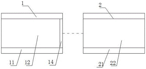
[0032] Such as figure 2 As shown, the electrical connector for preventing secondary arc of the present invention includes a first connecting end 1 and a second connecting end 2 .

[0033] The first connecting end 1 includes a first insulating layer 11 and a first conductor 12, and the second connecting end 2 includes a second insulating layer 21 and a second conductor 22; the electrical contact surface on the front side of the first conductor 12 is provided with a conductive medium layer 14. The conductive medium layer 14 has fluidity.

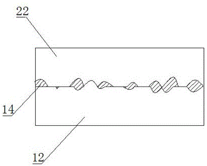
[0034] Such as image 3 , 5 As shown, when the first connection end 1 and the second connection end 2 are electrically connected, the first conductor 12 and the second conductor 22 approach each other at a certain speed, and due to the kinetic energy difference between the first conductor 12 and the second conductor 22, After the first conductor 12 and the second conductor 22 collide and conduct electricity for the first time, the gap gen...


PUM


Abstract

The invention relates to the electric connection field of a connector, especially to an electric connection method for secondary arc prevention. When two electric connecting terminals are connected, a gap between the two electric connecting terminals is filled with a flowable conducting medium. During the connection process of the two electric connecting terminals, electric contact surfaces of the electric connecting terminals are uneven and many discharging tips are formed; and a kinetic energy difference is generated between the two electric connecting terminals during the connection process. Therefore, the electric contact surfaces are in primary contact, separation of the electric contact surfaces is caused by the impulsive effect; and a secondary arc is generated at the gap caused by separation. However, when the flowable conducting medium is employed, the impulse generated by contact of the two electric connecting terminals can be cushioned and conductivity during separation of the electric contact surfaces can be guaranteed, thereby preventing the secondary arc.

Description

technical field [0001] The invention relates to the field of electrical connection of connectors, in particular to an electrical connection method for preventing secondary arcs. Background technique [0002] Arc is a gas discharge phenomenon, the instantaneous spark generated by the current passing through some insulating medium (such as air). Electrons escape from the contact metal surface due to an electron emission (thermionic emission, field emission or photoemission), and the gas atoms or molecules in the gap will generate electrons and ions due to ionization (impact ionization, photoionization and thermal ionization). In addition, electron or ion bombardment of the emitting surface causes secondary electron emission. When the ion concentration in the gap is high enough, the gap is electrically broken down and an arc is generated. It not only has a great destructive effect on the contacts, but also prolongs the time to disconnect the circuit. [0003] In the process ...

Claims


Application Information

Patent Timeline
IPC IPC(8): H01R13/53H01R13/03
CPCH01R4/04H01R13/03H01R13/53
Inventor 周刚
Owner ARGANGLE TECH
Why Eureka
Try Eureka