Permanent magnet speed regulation automobile driving electric motor

A technology for driving motors and permanent magnet speed regulation, applied in the direction of magnetic circuit rotating parts, magnetic circuits, electric components, etc., can solve the problem of single design of rotor stamping magnetic steel slots and magnetic isolation bridges, short circuit of excitation magnetic flux, and reduction of mechanical Performance and other issues, to achieve excellent electromagnetic performance, reduce starting current, and avoid magnetic short circuit effects

Inactive Publication Date: 2016-11-16
南京高传电机制造有限公司
View PDF6 Cites 1 Cited by
  • Summary
  • Abstract
  • Description
  • Claims
  • Application Information

AI Technical Summary

Problems solved by technology

If there is no magnetic isolation bridge or the magnetic isolation bridge is too wide, part of the excitation flux generated by the permanent magnets in the magnetic steel slot will be short-circuited, so that useful work cannot be done through the main magnetic circuit, reducing the efficiency of the motor
However, in the prior art, the design of the magnetic steel slots and magnetic isolation bridges of the rotor punching sheet is single and the magnetic flux leakage coefficient is large.
In order to reduce the flux leakage coefficient, if the width of the magnetic isolation bridge of the rotor punching sheet in the prior art is reduced, the mechanical performance will be greatly reduced.

Method used


Image

  • Permanent magnet speed regulation automobile driving electric motor
  • Permanent magnet speed regulation automobile driving electric motor
  • Permanent magnet speed regulation automobile driving electric motor

Examples


no. 1 example

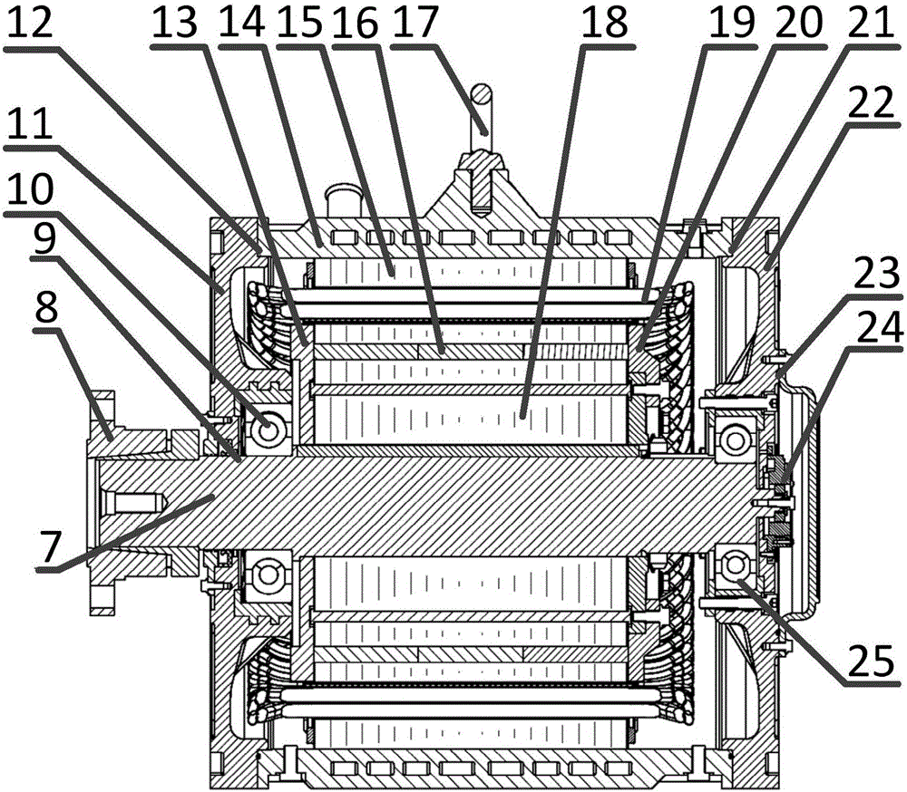
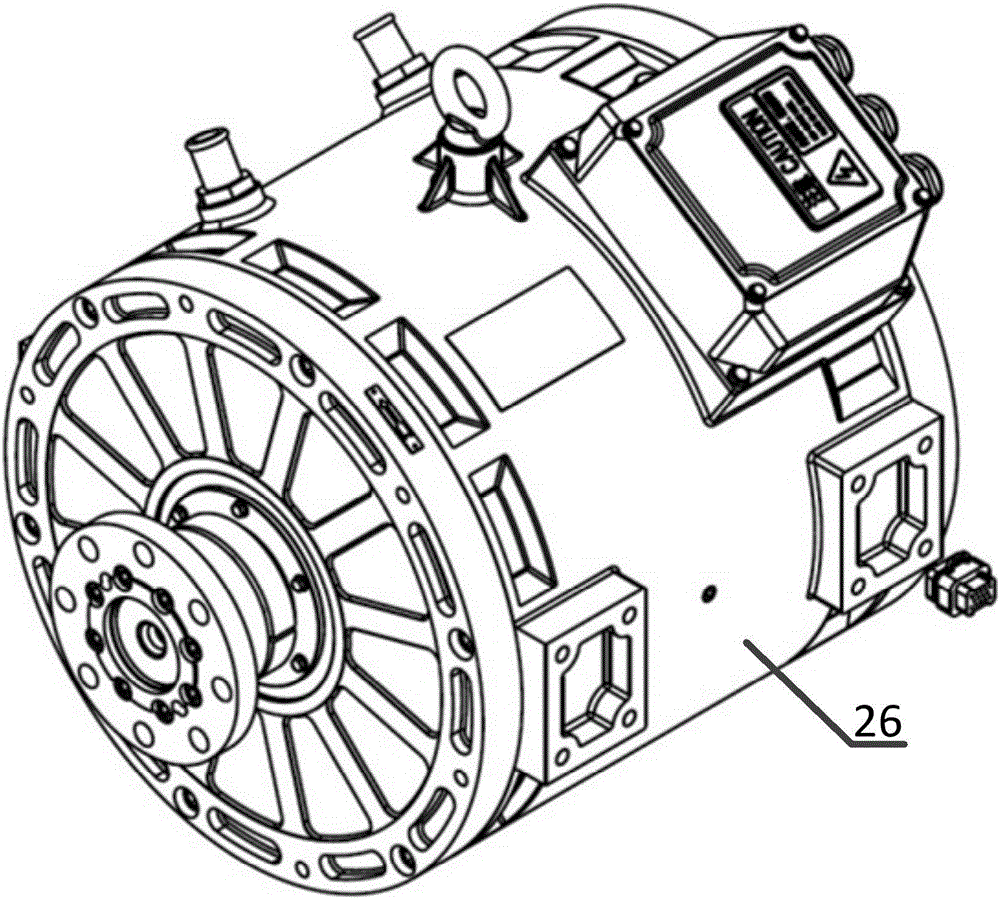
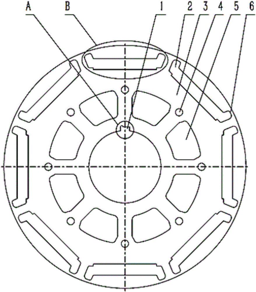
[0050] Such as figure 1 with figure 2 As shown, the present invention proposes a permanent-magnet speed-regulating automobile drive motor, wherein the permanent-magnet speed-regulating automobile drive motor is sequentially provided with a shaft 7, a rotor core 18, a rotor magnet 16, and a coil 19 from the inner layer to the outer layer. , The stator core 15 and the casing 26, where, such as image 3 with Figure 5 As shown, the rotor core 18 is a plurality of mutually overlapping rotor punching pieces 28. The rotor punching piece 28 includes a rotor punching piece body 3 and a magnetic steel slot 2 arranged on the rotor punching piece body 3; the magnetic steel slots 2 include mutually communicating The central groove 202, the magnetic steel stop groove 203, the first extension wing groove 201 and the second extension wing groove 204, and the magnetic steel stop groove 203, the first extension wing groove 201 and the second extension wing groove 204 surround the center The gro...

no. 2 example

[0089] The second embodiment of the present invention will be described below.

[0090] Such as Figure 4 As shown, the difference between this embodiment and the first embodiment is that in the second embodiment, twelve magnetic steel grooves 2 are uniformly opened on the rotor punch body 3, and the first magnetic steel groove 2 on both sides of each magnetic steel groove 2 A plurality of magnetic isolation bridges 6 are formed between the upper edges of the extended wing groove 201 and the second extended wing groove 204 and the outer edge of the rotor punch body 3, and a plurality of positioning protrusions 29 are provided on the inner side of the rotor punch body 3. And positioning groove 30. In addition, the second embodiment can adopt other features of the first embodiment. Therefore, for the sake of brevity, only the differences of the second embodiment are described below.

[0091] In this embodiment, the ventilation holes 5 can be arranged corresponding to the magnetic st...


PUM

PropertyMeasurementUnit
Widthaaaaaaaaaa

Abstract

The invention provides a permanent magnet speed regulation automobile driving electric motor which is provided with a rotating shaft, a rotor iron core, a rotor magnetic steel member, a wire coil, a stator iron core and a casing that are all order arranged from an inner layer to an outer layer; the rotor iron core consists of a plurality of overlapping rotor punching sheets, the rotor punching sheets comprise rotor punching sheet bodies and magnetic steel grooves arranged on the rotor punching sheet bodies; each magnetic steel groove comprises a central groove, a magnetic steel spigot groove, a first extending wing groove and a second extending wing groove that are all communicated with each other. On one hand, in the permanent magnet speed regulation automobile driving electric motor, a magnetic flux leakage coefficient can be effectively reduced via the rotor punching sheets, magnetic steel demagnetization risk can be reduced, great mechanical performance can be realized, electric motor efficiency can be improved, electromagnetic noise can be lowered, a starting current can be reduced, and torque and limit speed of the electric motor can be increased. On the other hand, design of magnetism isolating bridges on the rotating punching sheets can help effectively prevent two ends of the magnetic steel member can be prevented from being magnetically short-circuited.

Description

Technical field [0001] The invention relates to a permanent magnet motor, in particular to a permanent magnet speed regulating automobile drive motor. Background technique [0002] The motor is mainly composed of a rotor part and a rotor part, and the rotor is formed by stacking each rotor punching piece. The rotor punching piece is a key component in the motor, and its inner and outer circle size, slot size, and size have a direct impact on the efficiency of the motor. At present, automobile motors on the market cannot achieve higher efficiency, better reliability and higher limit speed. And there are defects such as large electromagnetic noise and small torque. The efficiency of the motor is closely related to the flux leakage coefficient of the rotor punch. If there is no magnetic separation bridge or the magnetic separation bridge is too wide, part of the excitation magnetic flux generated by the permanent magnets in the magnetic steel channel will be short-circuited, whic...

Claims


Application Information

Patent Timeline
IPC IPC(8): H02K1/27H02K1/32H02K5/20H02K5/173H02K5/124H02K11/20
CPCH02K1/2706H02K1/32H02K5/124H02K5/173H02K5/20H02K2213/03
Inventor 廖恩荣薛文彦王恒俭李更生蔡军菲张涛陈荷雅
Owner 南京高传电机制造有限公司
Why Eureka
Try Eureka