Switched reluctance motor of rechargeable ship and switched reluctance drive device

A switched reluctance motor and switched reluctance drive technology, applied in electromechanical devices, electrical components, etc., can solve problems such as torque ripple, unreliability, and potential safety hazards, reduce unilateral deformation, and increase quasi-salient poles Quantity, the effect of reducing torque ripple

Inactive Publication Date: 2016-11-16
安徽浙科智创系统服务有限公司
View PDF11 Cites 2 Cited by
  • Summary
  • Abstract
  • Description
  • Claims
  • Application Information

AI Technical Summary

Problems solved by technology

[0002] With the development of electromagnetic technology and power electronics technology, motors have been greatly improved in terms of efficiency and speed regulation performance. On the one hand, it solves the unreliability and safety hazards of brush motor commutation. , flexible control, good speed regulation performance and efficiency. For the existing switched reluctance motor, the stator specifications are the same, which often causes magnetic saturation and affects the rotor rotation effect. The rotor rotation on the existing switched reluctance motor is determined by The excitation magnetic field of the stator is coupled in the salient pole rotor, which is caused by the component of the magnetic pulling force in the tangential direction of the rotor based on the principle of "minimum reluctance". This determines that the reluctance motor has a simple structure, firmness, convenient processing, and low cost. features
However, the salient pole structure of the reluctance motor and its switch control characteristics also make its torque ripple, vibration, and noise a problem that restricts its development

Method used


Image

  • Switched reluctance motor of rechargeable ship and switched reluctance drive device
  • Switched reluctance motor of rechargeable ship and switched reluctance drive device
  • Switched reluctance motor of rechargeable ship and switched reluctance drive device

Examples


Embodiment Construction

[0019] In order to make the technical means, creative features, objectives and effects of the present invention easy to understand, the present invention will be further explained below in conjunction with specific embodiments.

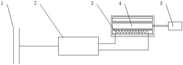
[0020] See Figure 1-Figure 5 , The present invention provides a technical solution: a switched reluctance motor and a switched reluctance drive device for a charging ship, including a ship power grid 1, a voltage converter 2, a phase winding 3, a switched reluctance motor 4 and a load 5, and a ship power grid 1 The left end of the voltage converter 2 is connected by a wire, and the right end of the voltage converter 2 is connected with the phase winding 3 by a wire. The phase winding 3 is installed in the switched reluctance motor 4, and the right end of the switched reluctance motor 4 is equipped with a load 5.

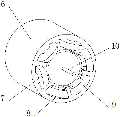
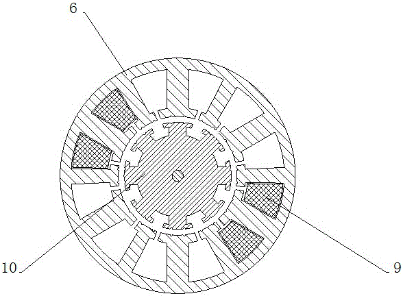
[0021] The structure of switched reluctance motor 4 is composed of stator mechanism 6, A phase coil 7, B phase coil 8, C phase coil 9 and rotor...


PUM


Abstract

The invention provides a switched reluctance motor of a rechargeable ship and a switched reluctance drive device. The switched reluctance motor comprises a housing, broad stator tooth poles, narrow stator tooth poles, stator auxiliary slots I, stator auxiliary slots II, rotor tooth poles, rotor auxiliary slots and a rotor main body, wherein six broad stator tooth poles are fixed on the inner wall of the housing at equal distances; six narrow stator tooth poles are arranged on the inner wall of the housing at equal intervals; two stator auxiliary slots I are processed in the outer end of each broad stator tooth pole; two stator auxiliary slots II are processed in the outer end of each narrow stator tooth pole; the six broad stator tooth poles are wound by an A-phase coil, a B-phase coil and a C-phase coil respectively; eight rotor tooth poles are fixed at the outer end of the rotor main body at equal distances; and two rotor auxiliary slots are processed in the outer end of each rotor tooth pole. By the switched reluctance motor of the rechargeable ship, magnetic saturation is prevented, the rotating effect of a rotor is improved, the number of quasi-salient poles is increased, the unilateral deformation is reduced and torque ripples, air pulsation and acoustical power are reduced.

Description

Technical field [0001] The invention relates to a switch reluctance motor and a switch reluctance drive device of a charging ship, belonging to the field of electromechanical technology. Background technique [0002] With the development of electromagnetic technology and power electronic technology, motors, both in terms of efficiency and speed regulation performance, have been greatly improved. On the one hand, it solves the unreliability and safety hazards of brushed motors when commutation. On the other hand, , Flexible control, good speed regulation performance and efficiency. For the existing switched reluctance motors, the same stator specifications often cause magnetic saturation and affect the rotor rotation effect. The rotor rotation on the existing switched reluctance motors is caused by The stator excitation magnetic field is coupled in the salient pole rotor, and the magnetic pulling force generated based on the principle of "minimum reluctance" is caused by the compo...

Claims


Application Information

Patent Timeline
IPC IPC(8): H02K29/03
CPCH02K29/03
Inventor 朱成野
Owner 安徽浙科智创系统服务有限公司
Why Eureka
Try Eureka