
Lifting structure of axle assembly

A lifting structure and wheel shaft technology, which is applied in vacuum cleaners, household appliances, cleaning equipment, etc., can solve problems such as high production costs, high maintenance costs, and complex structures

Active Publication Date: 2019-01-15
SUZHOU CHUNJU ELECTRIC CO LTD
View PDF6 Cites 0 Cited by
  • Summary
  • Abstract
  • Description
  • Claims
  • Application Information

AI Technical Summary

Problems solved by technology

However, the lifting structure of the wheel shaft assembly of the traditional vacuum cleaner is realized by multiple parts, which has complex structure, high production cost and high maintenance cost.

Method used


Image

  • Lifting structure of axle assembly
  • Lifting structure of axle assembly
  • Lifting structure of axle assembly

Examples


Embodiment Construction

[0036] Preferred embodiments of the present invention will be described in detail below in conjunction with the accompanying drawings.

[0037] In order to achieve the purpose of the present invention, in some embodiments of the lifting structure of the wheel axle assembly,

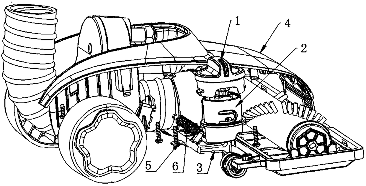
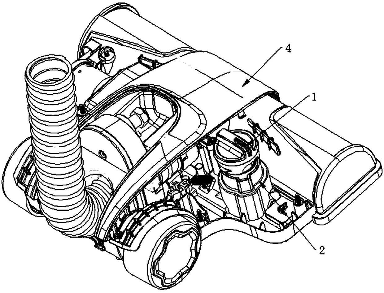
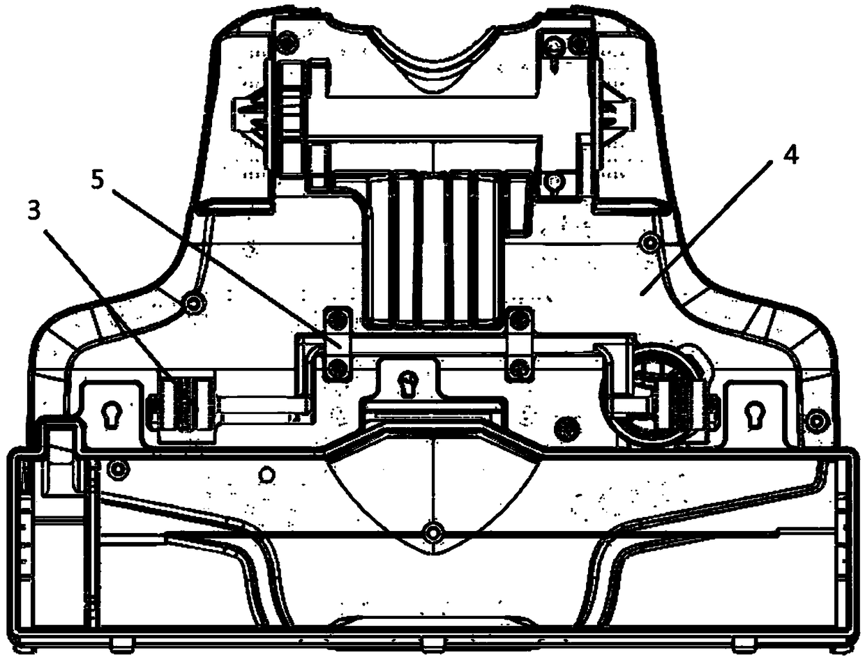
[0038] Such as Figure 1-8 As shown, the axle assembly lifting structure is arranged on the vacuum cleaner housing 4, including: a knob 1, a cam 2 and an axle assembly 3, the knob 1 is connected with the rotating part 21 of the cam 2, and a plurality of continuous With the uneven positioning groove 22, the axle assembly 3 is connected with the end of the cam 2 in contact. The knob 1 is provided with a groove 11 , and the knob part of the cam 2 is provided with a protrusion 23 matching the groove 11 .

[0039] Adjacent positioning grooves 22 are smoothly transitioned in circular arcs. The groove inner wall of the positioning groove 22 is a circular arc surface.

[0040] The axle assembly 3 includes: a ...


PUM


Abstract

The invention discloses a wheel axle assembly lifting structure arranged on a dust collector shell. The wheel axle assembly lifting structure comprises a rotary knob, a cam and a wheel axle assembly. The rotary knob is in matched connection with a rotary portion of the cam. The end of the cam is provided with a plurality of continuous uneven positioning grooves. The wheel axle assembly is in contact connection with the end of the cam. The wheel axle assembly lifting structure is simple in structure, convenient and fast to operate, low in cost and capable of effectively adjusting the terrain clearance of the wheel axle assembly.

Description

technical field [0001] The invention relates to a vacuum cleaner technology, in particular to a lifting structure of a wheel shaft assembly applied to a vacuum cleaner. Background technique [0002] With the improvement of productivity level, vacuum cleaners have gradually become a necessity of contemporary people's life. How to optimize the performance of vacuum cleaners has become a problem that manufacturers have been thinking about. In order to allow the vacuum cleaner to be effectively applied to different occasions and carpets of different materials, the manufacturer realizes this by adjusting the height of the wheel shaft assembly from the ground. However, the lifting structure of the axle assembly of the traditional vacuum cleaner is realized by multiple parts, which has a complicated structure, high production cost and high maintenance cost. [0003] Therefore, there is an urgent need to propose a wheel axle assembly lifting structure that has a simple structure a...

Claims


Application Information

Patent Timeline
Patent Type & Authority Patents(China)
IPC IPC(8): A47L9/04A47L9/00
CPCA47L9/00A47L9/0455A47L9/0494
Inventor 严荣伟
Owner SUZHOU CHUNJU ELECTRIC CO LTD
Learn More