
Sighting target display system and sighting target display optimization method based on brain wave detection

An optimization method and display system technology, which is applied in the fields of eye testing equipment, diagnostic recording/measurement, medical science, etc., can solve problems such as unfavorable observation of the subject, replacement of visual targets, and adjustment of visual target sizes, etc., to achieve Conducive to observation, the effect of strong intelligence

Inactive Publication Date: 2016-11-23
ZHEJIANG SCI-TECH UNIV
View PDF7 Cites 5 Cited by
  • Summary
  • Abstract
  • Description
  • Claims
  • Application Information

AI Technical Summary

Problems solved by technology

[0006] The above two optotype display methods can satisfy the use of vision tests, but all require the subject to make corresponding output (voice, body or button) according to the optotype observed by the subject to replace the optotype. If the subject does not make any output, the medical staff or the display screen cannot replace the visual target, so that the display of the visual target cannot be fully intelligent
[0007] In addition, the visual distance between the existing visual acuity chart or the visual target display screen and the subject is fixed, and the display of the visual target cannot be adjusted according to the visual distance between the test subject and the visual acuity chart or visual target display screen. The size of the displayed visual target is not conducive to the observation of the subject

Method used


Image

  • Sighting target display system and sighting target display optimization method based on brain wave detection
  • Sighting target display system and sighting target display optimization method based on brain wave detection
  • Sighting target display system and sighting target display optimization method based on brain wave detection

Examples


Embodiment Construction

[0041] In order to make the technical means, creative features, goals and effects achieved by the present invention easy to understand, the present invention will be further described below in conjunction with specific embodiments.

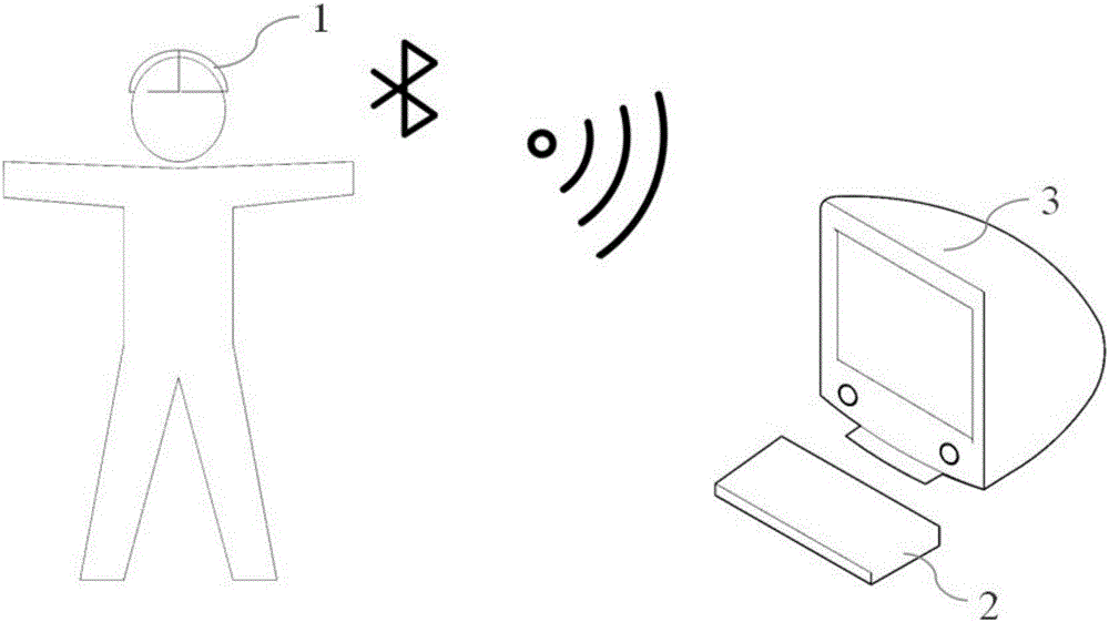
[0042] Such as figure 1 As shown, the present application provides a visual target display system based on brain wave detection, which can detect changes in the brain wave frequency of the subject in the process of observing the visual target, because the brain wave generated by the human body in different environments The frequency is different, therefore, it can be judged whether the subject's judgment on the optotype is correct according to it, so as to change the optotype displayed on the optotype display unit. The system includes an electroencephalogram detector 1 for detecting the brain wave frequency of the subject, a control for receiving the brain wave frequency of the subject, processing the frequency, and controlling the visual target d...


PUM


Abstract

The invention discloses a sighting target display system and a sighting target display optimization method based on brain wave detection, and relates to a sighting target display system and a sighting target display method. The system comprises a brain wave detector, a control unit and a sighting target display unit; an output of the brain wave detector is connected with one path of input of the control unit; an output of the control unit is connected with an input of the sighting target display unit. The sighting target display system and the sighting target display optimization method which are disclosed by the invention have higher intellectualization, and can implement automatic replacement of a sighting target without enabling a detected person to output the observed sighting target in a voice, gesture or key mode; the sighting target display system and the sighting target display optimization method which are disclosed by the invention implement regulation on the size of the sighting target displayed on the sighting target display unit according to a sighting distance between the sighting target display unit and the detected person, and are more beneficial for the detected person to observe.

Description

technical field [0001] The invention belongs to an optotype display system and an optotype display optimization method, in particular to an optotype display system and an optotype display optimization method based on brain wave detection. Background technique [0002] With the continuous advancement of the information age, the implementation of vision testing methods is also constantly improving, gradually evolving from paper-based vision chart testing to today's intelligent vision testing combined with hardware and software. However, whether it is a paper-based vision test or an intelligent vision test that combines software and hardware, it requires the assistance of an eye chart. The specific test methods are as follows: First, through the medical staff to indicate a specific visual mark in the eye chart, the testee makes corresponding gestures or voice notifications according to the visual mark he sees, or through buttons, the medical staff Judging the output of the sub...

Claims


Application Information

Patent Timeline
IPC IPC(8): A61B3/032A61B5/0484
CPCA61B3/0016A61B3/032A61B5/378
Inventor 洪榛周丽丹屠碧琪马徐峰
Owner ZHEJIANG SCI-TECH UNIV
Features
  • Generate Ideas
  • Intellectual Property
  • Life Sciences
  • Materials
  • Tech Scout
  • Unparalleled Data Quality
  • Higher Quality Content
  • 60% Fewer Hallucinations
Learn More