A source dismantling auxiliary device for medical radioactive source

An auxiliary device and radioactive source technology, applied in radiation therapy, X-ray/γ-ray/particle irradiation therapy, treatment, etc., can solve the problem that the cobalt source loading and unloading operation cannot be carried out smoothly, the locking parts are oxidized and corroded, and the cobalt source cannot be separated, etc. problem, to solve the problem of insufficient extraction force, improve the efficiency of disassembly and assembly, and achieve the effect of rapid replacement

Active Publication Date: 2017-05-24
SHIJI JINQIAO DATA SYST WUHAN
View PDF6 Cites 0 Cited by
  • Summary
  • Abstract
  • Description
  • Claims
  • Application Information

AI Technical Summary

Problems solved by technology

As a special equipment that can realize safe loading and unloading source operation, the above structure does serve a certain purpose of loading and unloading source operation. However, in practical application, it is found that this equipment still has the following problems: due to the attenuation of cobalt-60 as a radioactive source, every The replacement period of the cobalt source of each equipment is 6-8 years
Due to the water vapor in the air, there will be oxidation and corrosion of different sizes on the surface of the locking parts for a long time, and the locking parts will be stuck due to corrosion.
However, the maximum pulling force of 10kg calibrated by the current manipulator in its best posture cannot separate the cobalt source from the stuck positioning ring at all, resulting in the unsmooth loading and unloading of the cobalt source.

Method used


Image

  • A source dismantling auxiliary device for medical radioactive source
  • A source dismantling auxiliary device for medical radioactive source
  • A source dismantling auxiliary device for medical radioactive source

Examples


Embodiment Construction

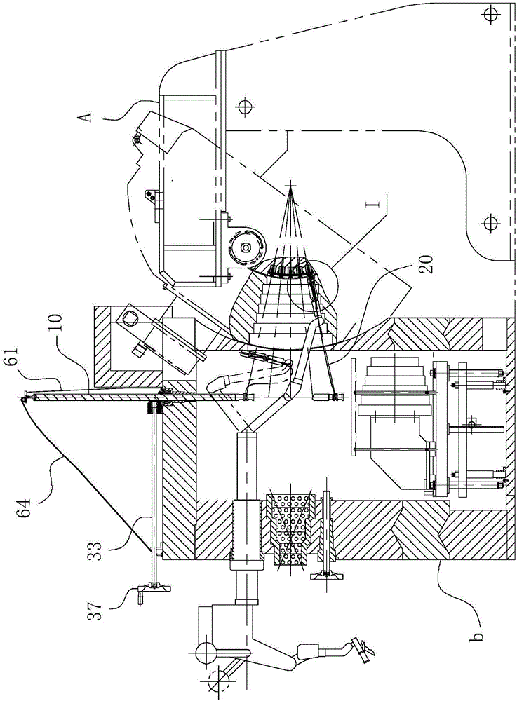
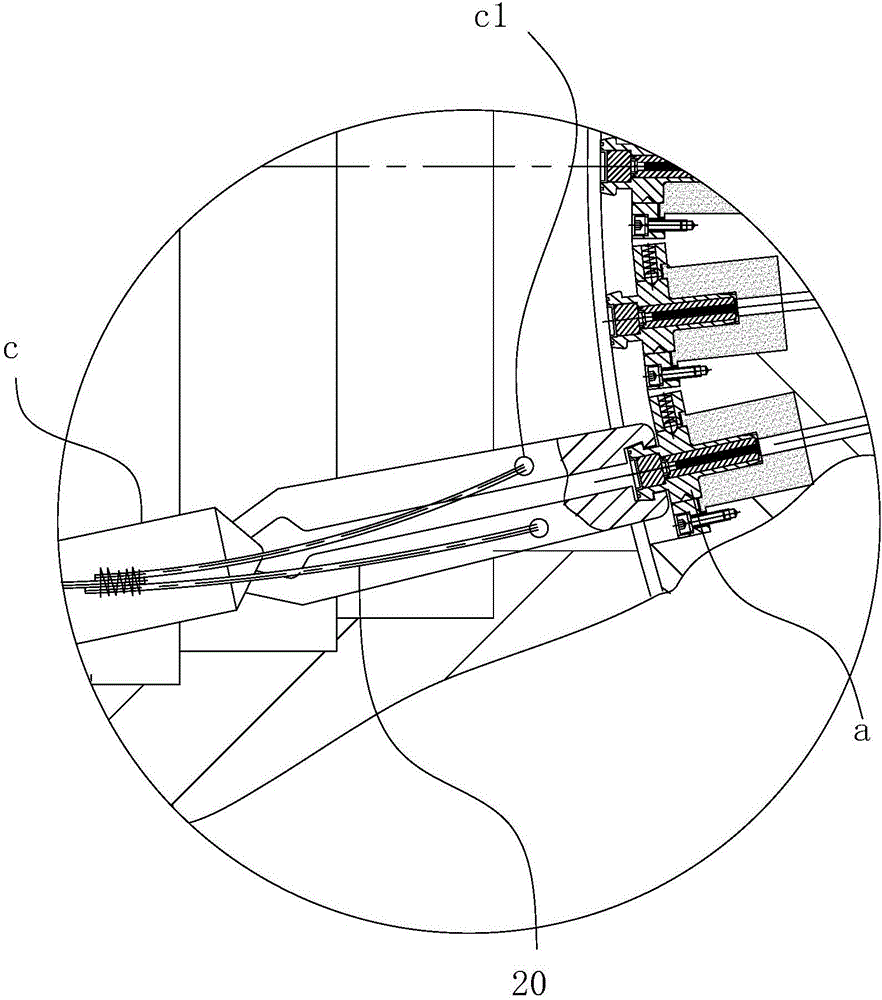
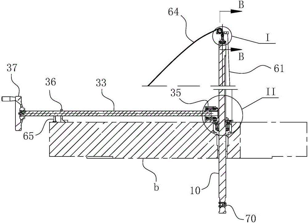
[0040] For ease of understanding, the specific implementation structure and workflow of the present invention are described below in conjunction with the accompanying drawings:

[0041] The original design intention of the present invention is to provide an extra pulling force to the manipulator at the source loading machine when the traditional source loading machine unloads the source, so that the cobalt source can be reliably separated from the installation hole. Under the above thinking, the present invention adopts such as Figure 1-7 construction shown. It should be noted, Figure 1-7 The structure shown is an example of the loading and unloading of the source-loading equipment in the body, which is embodied in drilling a rotary hole at the top shield plate of the heat chamber b, and then loading the device. For the head-mounted source equipment, the turning holes should be drilled at the shielding plates on both sides of the heat chamber b. At this time, the shaft of ...


PUM


Abstract

The invention belongs to the field of radiation source disassembly devices, and particularly relates to an auxiliary source disassembly device for a medical radiation source. The device at least comprises a source pulling guide rod; the source pulling guide rod penetrates through a hot chamber from the exterior of the hot chamber and extends into the hot chamber, and rotary cooperation is formed between the source pulling guide rod and the chamber wall of the hot chamber; a pulling rope is arranged at the end, located in the hot chamber, of the source pulling guide rod, and the pulling rope and a hook-shaped chunk arranged on a manipulator are fixedly connected with each other; when the source pulling guide rod rotates and drives the pull rope to generate a winding action acted around a rod body of the source puling guide rod, the force applying direction of the pulling rope relative to the hook-shaped chunk arranged on the manipulator is same as the force applying direction that the hook-shaped chunk arranged on the manipulator pulls out a cobalt source; the device further comprises a lifting driving portion for driving the source pulling guide rod to do reciprocating linear action and a rotary driving portion for controlling the source pulling guide rod to do rotary action. The device can be used by cooperating with an existing conventional source assembly machine, therefore, the pulling force of a manipulator arranged in the existing source assembly machine is effectively increased, and then the quick replacement requirement of the cobalt source is finally achieved.

Description

technical field [0001] The invention belongs to the field of radioactive source disassembly and assembly equipment, and in particular relates to a source disassembly auxiliary device for medical radioactive sources. Background technique [0002] Gamma Knife is a non-interventional radiotherapy device used to treat cancer; it uses the gamma rays generated by cobalt-60 to selectively determine intracranial or internal diseased tissues as targets based on the principle of stereogeometric orientation A one-time high-dose focused irradiation is performed to cause focal necrosis or functional changes, and finally achieve the purpose of treating the disease. Gamma Knife has the advantages of accurate target, high dose rate, short treatment time and high tumor control rate, so it has been widely used at home and abroad in recent years. [0003] At present, most of the conventional source replacement methods used in practice use a special equipment called loading (unloading) cobalt ...

Claims


Application Information

Patent Timeline
Patent Type & Authority Patents(China)
IPC IPC(8): A61N5/10
CPCA61N5/1007A61N2005/1009A61N2005/101A61N2005/1019A61N2005/1092
Inventor 周然华杨劲松
Owner SHIJI JINQIAO DATA SYST WUHAN
Why Eureka
Try Eureka