Ultrasonic transducer with vibration reduction function

An ultrasonic and transducer technology, applied in the field of ultrasonic transducers, can solve the problems such as the decrease in the repeatability of the transducer positioning accuracy, the inability to produce high-precision products, and the inability to guarantee the stability of the transducer, so as to save post-maintenance. , avoid errors, improve the effect of precision

Active Publication Date: 2016-11-23
无锡德众超声技术有限公司
View PDF6 Cites 4 Cited by
  • Summary
  • Abstract
  • Description
  • Claims
  • Application Information

AI Technical Summary

Problems solved by technology

When the transducer is working, the external pressure on the transducer will compress the rubber ring at the node. Due to factors such as the softness and hardness of the rubber ring, aging, and the temperature difference during work, the position of the rubber ring will change, causing the transducer to The repeated positioning accuracy of up, down, left, and right is greatly reduced, and the stability of the transducer during long-term use cannot be guaranteed, and high-precision products cannot be produced. When producing low-precision products, the rubber ring must be jacked up to replace it, which is time-consuming and labor-intensive.

Method used


Image

  • Ultrasonic transducer with vibration reduction function

Examples


Embodiment Construction

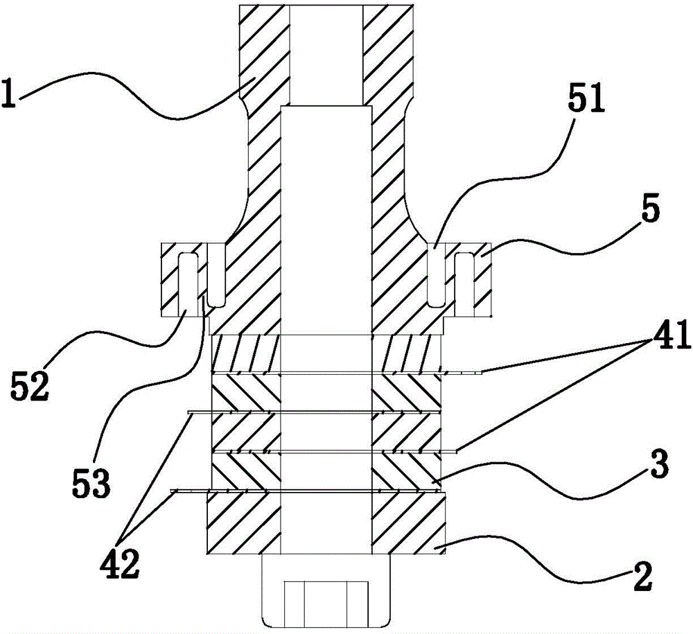
[0014] like figure 1 As shown, the present invention provides an ultrasonic transducer with vibration damping function, comprising a front cover 1 and a rear cover 2, and between the front cover 1 and the rear cover 2 are a plurality of ceramic sheets arranged at intervals 3 and electrode pads. In practical applications, the number of ceramic sheets 3 and electrode sheets arranged at intervals between the front cover plate 1 and the rear cover plate 2 are both two, four or six. In this embodiment, four ceramic sheets 3 and four electrode sheets are arranged between the front cover plate 1 and the rear cover plate 2, and the ceramic sheets 3 and the electrode sheets are arranged at intervals. The electrode sheet includes a positive electrode sheet 41 and a negative electrode sheet 42, and the positive electrode sheet 41 and the negative electrode sheet 42 are spaced apart from each other. The ceramic sheet 3 is in contact with the front cover 1 , and the electrode sheet is in...


PUM


Abstract

The invention discloses an ultrasonic transducer with a vibration reduction function. The ultrasonic transducer with the vibration reduction function comprises a front cover plate and a rear cover plate. A plurality of ceramic wafers and electrodes are arranged between the front cover plate and the rear cover plate in a spaced mode. The ultrasonic transducer with the vibration reduction function is characterized in that a double-groove structure is arranged at the joint of the front cover plate and comprises an inner groove and an outer groove; the inner groove is a blind groove, the outer groove is also a blind groove, the inner groove and the outer groove are open in opposite directions, and a vibration reduction wall is arranged between the inner groove and the outer groove; and threads are arranged outside the double-groove structure. According to the ultrasonic transducer with the vibration reduction function, the thicknesses of the bottoms of the inner groove and the outer groove in the joint are smaller than 1 mm, and thus vibration is weak; the vibration reduction wall between the outer groove and the inner groove of a flange has the vibration reduction function and can eliminate vibration on the joint, errors caused by vibration are avoided, and equipment precision is improved; and the ultrasonic transducer is connected with an external component through the threads outside the flange, the situation that damage is caused due to pressure when a rubber ring is used, and consequentially up-down or left-right errors are caused is avoided, and equipment precision is improved.

Description

technical field [0001] The invention belongs to a transducer, and more particularly relates to an ultrasonic transducer with a vibration reduction function. Background technique [0002] All ultrasonic equipment and instruments are composed of ultrasonic generator and ultrasonic acoustic assembly. The ultrasonic acoustic assembly is composed of ultrasonic transducers, horns, welding heads and other parts connected in sequence. The ultrasonic transducer is one of the parts. core components. The ultrasonic transducer is a vibrating part when it works, and the connection between the ultrasonic transducer and the external parts is more important. The part where the ultrasonic transducer is connected to the external components is designed at the position with the weakest vibration, which is the node of the transducer. The vibration of the node will be different due to the different amplitude of the transducer. When the node of the ultrasonic transducer is connected to the outsi...

Claims


Application Information

Patent Timeline
Patent Type & Authority Applications(China)
IPC IPC(8): B06B1/06
Inventor 李振旭
Owner 无锡德众超声技术有限公司
Why Eureka
Try Eureka