A positioning device and positioning method for a stacking material channel

A positioning device and stacking technology, which is applied to the positioning device of the stacking channel and the field of the material channel, can solve the problems of inability to change models and realize long-term unmanned automation, etc., to achieve simple model changes and long-term unmanned The effect of automation and high positioning accuracy

Active Publication Date: 2018-08-31
宁夏巨能机器人股份有限公司
View PDF10 Cites 0 Cited by
  • Summary
  • Abstract
  • Description
  • Claims
  • Application Information

AI Technical Summary

Problems solved by technology

[0002] The feeding mechanism is an indispensable component in the automatic production line. There are many types of automatic feeding devices. According to the shape and size of the processed raw materials and blanks, they can be divided into sheet feeding devices, coil feeding devices, and strip feeding devices. And piece material loading, etc., now requires the design of automatic feeding mechanism to realize automatic feeding, eliminate accumulated errors, and reduce labor costs at the same time; in the existing automatic production equipment transmission channel, the roller logistics transmission channel and chain plate are generally used Logistics transmission material channel; the existing material transmission mechanism is mainly composed of rollers or chain plates, racks, brackets, outriggers, transmission devices and drive devices; Due to the positioning and storage problems of the existing transmission material channel, it must be manually fed in time, which cannot realize long-term unmanned automation and cannot be changed.

Method used


Image

  • A positioning device and positioning method for a stacking material channel
  • A positioning device and positioning method for a stacking material channel

Examples


Embodiment Construction

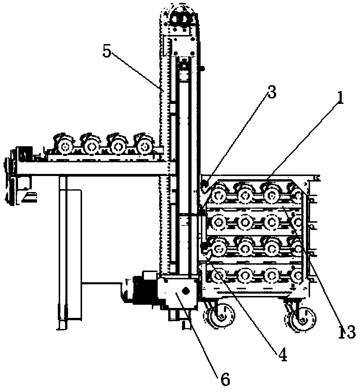
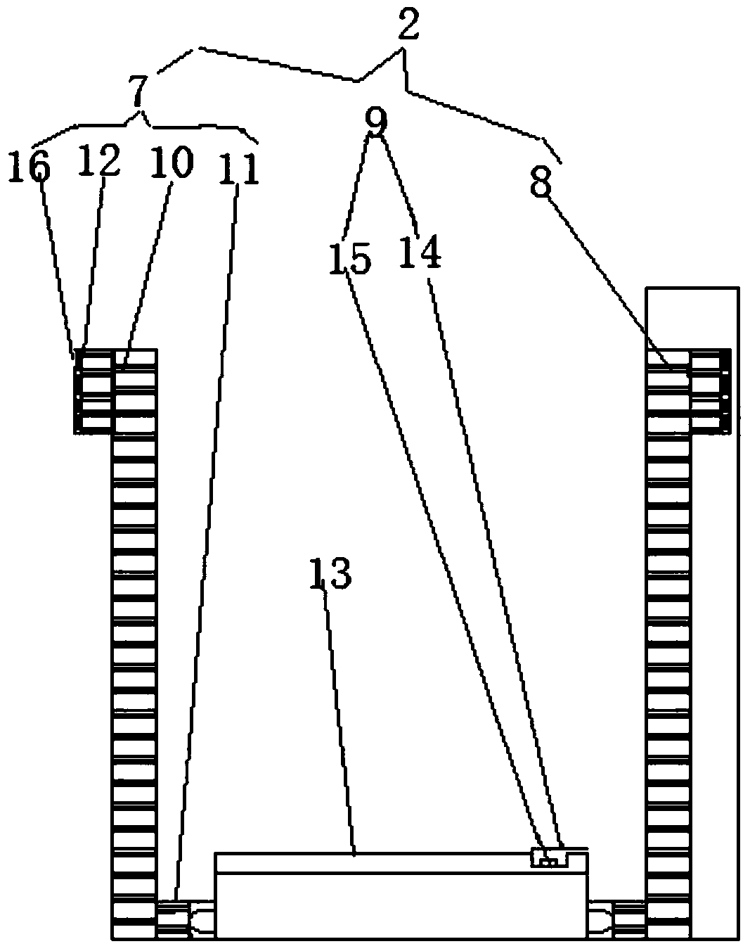
[0019] Such as figure 1 with figure 2 As shown, the positioning device of the stacking channel of the present invention includes a drawer-type stacking material box 1 and a positioning assembly 2, and a hanging column 3 arranged on the side of the drawer-type stacking box; the hanging column 3 passes through a hook 4 And the conveyor belt 5 is connected to the servo motor 6; the positioning assembly 2 includes a left grating positioning piece 7, a right grating positioning piece 8 and a layer grating positioning piece 9; the left grating positioning piece 7 and the right grating positioning piece 8 include a grating guide rail 10 , And a grating light-emitting element 11 installed on the grating guide rail at one end, and a grating light emitting element 11 installed on the side of the box at the other end; and a grating receiver 12 installed on the top of the other side of the grating rail; the layer grating positioning element 9 includes a drawer type The rail groove 14 on t...


PUM


Abstract

The invention discloses a positioning device for a stacking material way. The positioning device comprises a drawer type stacking material box, a positioning assembly and hanging columns arranged on the edge side of the drawer type stacking material box. The hanging columns are connected to a servo motor through hooks and a conveying belt. The positioning assembly comprises a left optical grating positioning piece, a right optical grating positioning piece and a layer optical grating positioning piece. The left optical grating positioning piece and the right optical grating positioning piece each comprise an optical grating guide rail, an optical grating light emitting piece with one end arranged on the optical grating guide rail and the other end installed on the edge side of a box body, and an optical grating receiving piece arranged on the top of the other side of the optical grating guide rail. The optical grating receiving pieces are connected to a controller, and the controller is connected with the servo motor. A positioning method for the above positioning device for the stacking material way comprises the following steps of position calibration, primary positioning and accurate positioning. According to the positioning device for the stacking material way and the positioning method for the positioning device, the drawer type stacking material box is used for storing materials, row dividing machining can be achieved through cooperation of the positioning device, and long-time unmanned automation can be achieved; and automatic elevating and servo positioning are achieved.

Description

Technical field [0001] The invention relates to a material channel, in particular to a positioning device and a positioning method of a stacking material channel, and belongs to the technical field of workpiece transmission. Background technique [0002] The feeding mechanism is an indispensable component of the automatic production line. There are many types of automatic feeding devices. According to the shape and size of the processed raw materials and blanks, they can be divided into sheet feeding devices, coil feeding devices, and strip feeding devices. For material loading, etc., it is now required to design an automatic feeding mechanism to realize automatic feeding, eliminate accumulated errors, and reduce labor costs; in the existing automatic production equipment transmission channels, roller logistics transmission channels and chain plates are generally used Logistics conveying channel; the existing conveying mechanism is mainly composed of rollers or chain plates, rack...

Claims


Application Information

Patent Timeline
Patent Type & Authority Patents(China)
IPC IPC(8): B23Q7/14B25H3/02
CPCB23Q7/14B25H3/021
Inventor 宋明安孙洁付焕清刘学平同彦恒李志博麻辉
Owner 宁夏巨能机器人股份有限公司
Why Eureka
Try Eureka