Pushing and cutting device

A cutting device and installation box technology, applied in special forming/shaping machines, wood processing appliances, manufacturing tools, etc., can solve the problems of low efficiency of manual cutting, work fatigue of staff, and high maintenance costs, and achieve strong novelty. , The effect of low maintenance cost and high work efficiency

Active Publication Date: 2016-11-23
山东龙鑫环保设备有限公司
View PDF10 Cites 36 Cited by
  • Summary
  • Abstract
  • Description
  • Claims
  • Application Information

AI Technical Summary

Problems solved by technology

[0002] With the development of society and the improvement of people's living standards, the quality requirements for various types of panels are relatively high when building and decorating houses. In order to ensure the quality of panels, they will be cut before finishing, but most of the existing enterprises All are manual cutting or human-driven cutting. Manual cutting has low work efficiency and uneven cutting, which will cause work fa

Method used


Image

  • Pushing and cutting device
  • Pushing and cutting device
  • Pushing and cutting device

Examples


Embodiment Construction

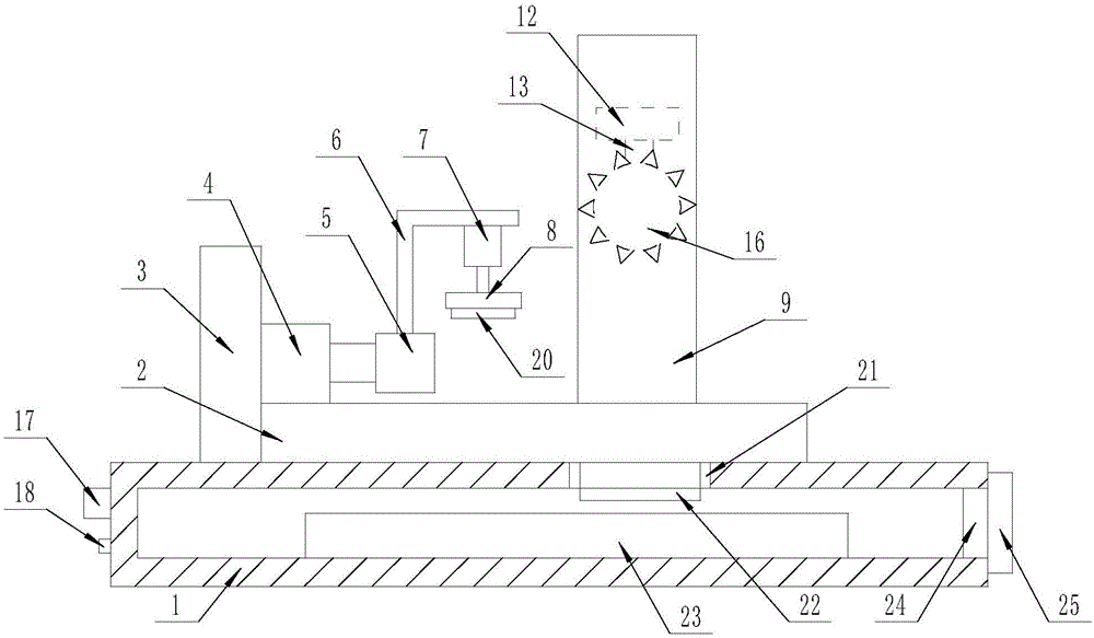
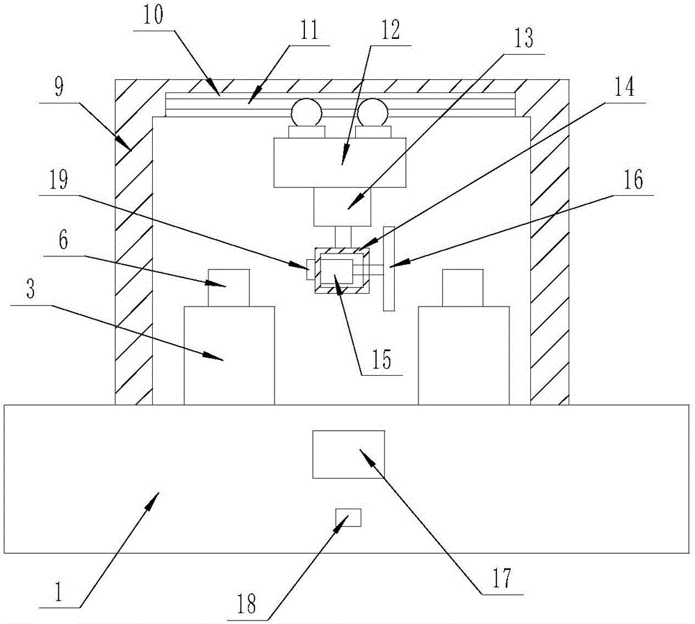
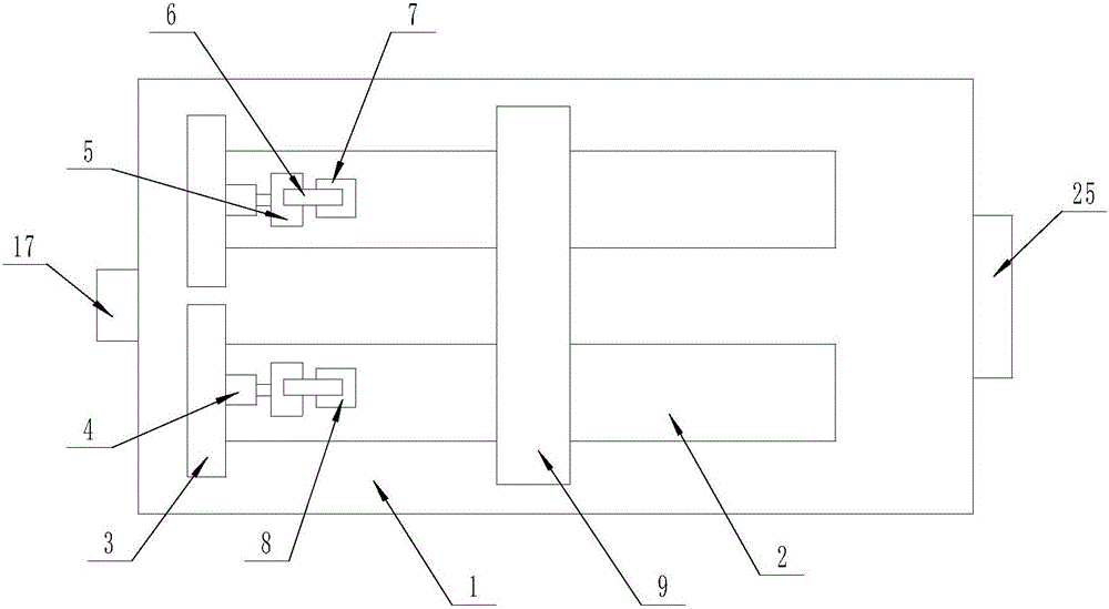
[0016] The present invention is specifically described below in conjunction with accompanying drawing, as Figure 1-3 As shown, a push cutting device includes a workbench (1), the interior of the workbench (1) is a cavity structure, the upper surface of the workbench (1) is provided with a group of carrier plates (2) parallel to each other, One end of each of the carrier plates (2) is provided with a top plate (3), and each of the top plates (3) is provided with a linear motor (4) with a telescopic end in a horizontal direction, and each of the linear motors (4) ) telescopic ends are all provided with a top block (5), each of the top blocks (5) is provided with an L-shaped bracket (6) on the upper surface, and each of the L-shaped brackets (6) is provided with a telescopic end on the lower surface Downward micro-telescopic cylinder (7), each of the micro-telescopic cylinders (7) is provided with a pressing plate (8) at the telescopic end, and the upper surface of the workbench...


PUM


Abstract

The invention discloses a pushing and cutting device. The pushing and cutting device comprises a worktable, wherein the interior of the worktable is a cavity structure; a group of loading plates parallel to each other are arranged on the upper surface of the worktable; an ejection plate is arranged at one end of each loading plate; a linear motor with a telescopic end in a horizontal direction is arranged on each ejection plate; an ejection block is arranged at the telescopic end of each linear motor; an L-shaped bracket is arranged on the upper surface of each ejection block; a micro telescopic cylinder with a downward telescopic end is arranged on the lower surface of each L-shaped bracket; a controller is arranged on one side surface of the worktable; a power interface is located under the controller and is electrically connected to the controller; the controller is electrically connected to the linear motors, the micro telescopic cylinders, an electric trolley, a telescopic cylinder and a rotating motor respectively. The pushing and cutting device has the advantages that the device is capable of automatically pushing and cutting, the personal safety of workers is protected, the device is capable of uniformly cutting, and the device is convenient and practical.

Description

technical field [0001] The invention relates to the field of push cutting, in particular to a push cutting device. Background technique [0002] With the development of society and the improvement of people's living standards, the quality requirements for various types of panels are relatively high when building and decorating houses. In order to ensure the quality of panels, they will be cut before finishing, but most of the existing enterprises All are manual cutting or human-driven cutting. Manual cutting has low work efficiency and uneven cutting, which will cause work fatigue to the staff. Artificially driven cutting, too close to the cutter, will cause danger if you are not careful, and there are potential safety hazards. Nowadays The cutting device has high maintenance cost and is not suitable for some small and medium-sized enterprises. In order to meet the market demand, better and more complete equipment is needed when manufacturing plates. In order to solve this k...

Claims


Application Information

Patent Timeline
IPC IPC(8): B27C5/02B27C5/06
CPCB27C5/02B27C5/06
Inventor 徐海慧张文文李宁宁刘向明
Owner 山东龙鑫环保设备有限公司
Why Eureka
Try Eureka