Injection device of precision injection machine

An injection device and injection molding machine technology, applied in the field of precision injection molding machines, can solve the problems of limited space, inability to assemble and apply the transmission structure, low energy consumption and low cost, and achieve small footprint, avoid accidental burns, and good use safety and reliability effects

Inactive Publication Date: 2016-11-23
JIANGSU TIANYUAN TEST EQUIP
View PDF1 Cites 2 Cited by
  • Summary
  • Abstract
  • Description
  • Claims
  • Application Information

AI Technical Summary

Problems solved by technology

[0003] However, due to the limited space in most laboratories at present, the energy consumption and expenditure are not high; therefore, the driving devices and transmission structures used in the above technical solutions to ensure the clamping force and injection pressure cannot be assembled and applied to conventional in the laboratory

Method used


Image

  • Injection device of precision injection machine
  • Injection device of precision injection machine
  • Injection device of precision injection machine

Examples


Embodiment Construction

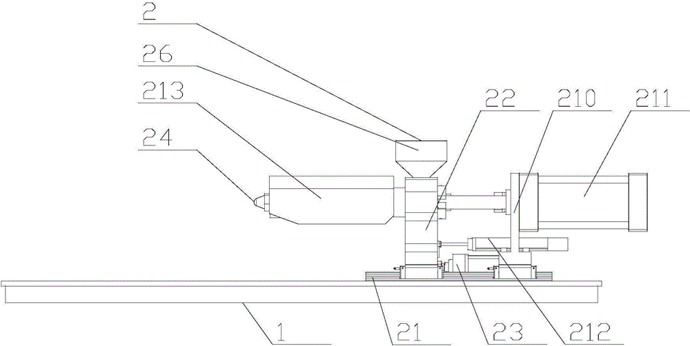
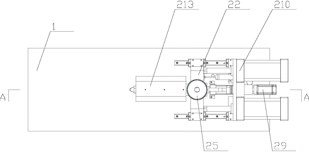
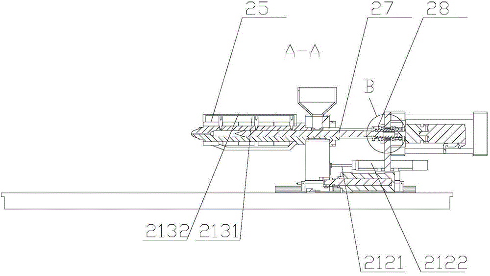
[0020] The present invention as Figure 1-5 As shown, including workbench 1, injection device 2 and clamping device 3,

[0021] The injection device 2 includes a slide rail 21, a base 22, a base driver 23, an injection tube 24, a heating jacket 25, a feed hopper 26, a screw 27, a coupling 28, a screw driver 29, a slide 210 and Slider driving device 211; the slide rail 21 and the base driving device 23 are arranged in the same direction, and are fixedly connected to the top surface of the workbench 1 of the injection molding machine, the base 22 and the slide seat 210 are arranged in parallel, and The bottoms of both are slidingly connected on the slide rail 21, so that the base 22 is driven by the base driving device 23 to do linear reciprocating motion along the slide rail 21; the sliding seat driving device 211 is fixedly connected to the sliding seat 210 The end surface of the base 22 is facing away from the base 22 and has a power rod that passes through the slide seat 21...


PUM


Abstract

The invention discloses an injection device of a precision injection machine, and relates to the field of precision injection machines. The injection device of the precision injection machine comprises a sliding rail, a base, a base driving device, an injection pipe, a heating sleeve, a material feeding hopper, a screw rod, a shaft coupler, a screw rod driving device, a sliding seat and a sliding seat driving device. During material feeding and injection, counter-acting force on the screw rod is directly transmitted to the sliding seat through a convex ring and a large bearing, and is finally borne by the sliding seat driving device for injecting a material, so that the screw rod driving device only supplies rotating torque during use and not bears the axial pressure; therefore, the screw rod driving device is effectively protected, and the low-power screw rod driving device with lower energy consumption and smaller size is adopted according to the space requirement of a laboratory; and furthermore, an additionally arranged heat isolation hood can effectively avoid accidental scalding of an operator during material machining, so that the injection device is extremely high in use safety and reliability.

Description

technical field [0001] The invention relates to the field of precision injection molding machines, in particular to the improvement of the injection device therein. Background technique [0002] At present, at present, most of the precision injection molding machines on the market are for the purpose of processing and production, and most of them have the characteristics of large energy consumption, high output, and large floor area. It is a Chinese patent document for "Miniature Precision Injection Molding Machine" with application number "201110360618.5". In this case, a technical solution is proposed to shorten the length of the injection molding machine and make its structure more compact. [0003] However, due to the limited space in most laboratories at present, the energy consumption and expenditure are not high; therefore, the driving devices and transmission structures used in the above technical solutions to ensure the clamping force and injection pressure cannot b...

Claims


Application Information

Patent Timeline
Patent Type & Authority Applications(China)
IPC IPC(8): B29C45/47B29C45/58B29C45/76B29C45/84
Inventor 王永
Owner JIANGSU TIANYUAN TEST EQUIP
Why Eureka
Try Eureka