Baby stroller

A technology of children's strollers and push rods, which is applied in the direction of trolleys, baby carriages/baby carriages, multi-axis children's carriages/cradle cars, etc., which can solve the problems of inconvenient operation and complicated structure of the stroller, and achieve easy storage and simple structure , small size effect

Active Publication Date: 2016-11-23
GOODBABY CHILD PROD CO LTD
7 Cites 4 Cited by

AI-Extracted Technical Summary

Problems solved by technology

However, the folding principles of the cart are various, which makes...

Method used

Specifically: the push rod assembly 1 comprises a lower push rod assembly 10, an upper push rod assembly 11 that is slidably connected with the lower push rod assembly 10, a locking mechanism that relatively locks the lower push rod assembly 10 and the upper push rod assembly 11 Parts, the lower end of the lower push rod assembly 10 is rotatably connected with the upper end of the front strut assembly 2 and the upper end of the rear strut assembly 3 through a linkage mechanism. The lower push rod assembly 10 is two hollow rods, and the upper push...

Abstract

The invention relates to a baby stroller. The baby stroller comprises a frame having an unfolding state and a folding state, wherein the frame comprises a push rod assembly, a front brace rod assembly, a rear brace rod assembly, a front wheel support assembly and a rear wheel support assembly, the lower end part of the push rod assembly, the upper end part of the front brace rod assembly and the upper end part of the rear brace rod assembly are connected in a rotating manner by virtue of a linkage mechanism, the lower end part of the front brace rod assembly is connected with the front wheel support assembly in a rotating manner, the lower end part of the rear brace rod assembly is connected with the rear wheel support assembly in a rotating manner, the front wheel support assembly is connected with the rear wheel support assembly in a sliding manner, when the frame is folded, the push rod assembly, the front brace rod assembly and the rear brace rod assembly are linked to rotate and draw close to the front wheel support assembly and the rear wheel support assembly, and the front wheel assembly is folded towards the rear wheel support assembly. By adopting a linked rotating structure, the baby stroller is simple in structure, convenient to operate, small in size of the frame after being folded, and convenient to store.

Application Domain

Carriage/perambulator with multiple axesHand carts

Technology Topic

Vehicle frameEngineering +1

Image

  • Baby stroller
  • Baby stroller
  • Baby stroller

Examples

  • Experimental program(1)

Example Embodiment

[0032] The following is an implementation of a linkage mechanism:
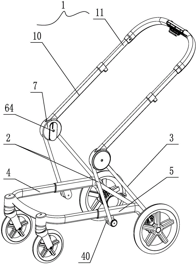
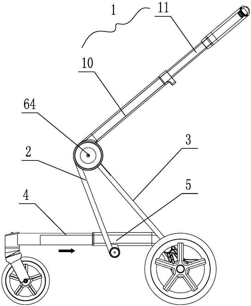
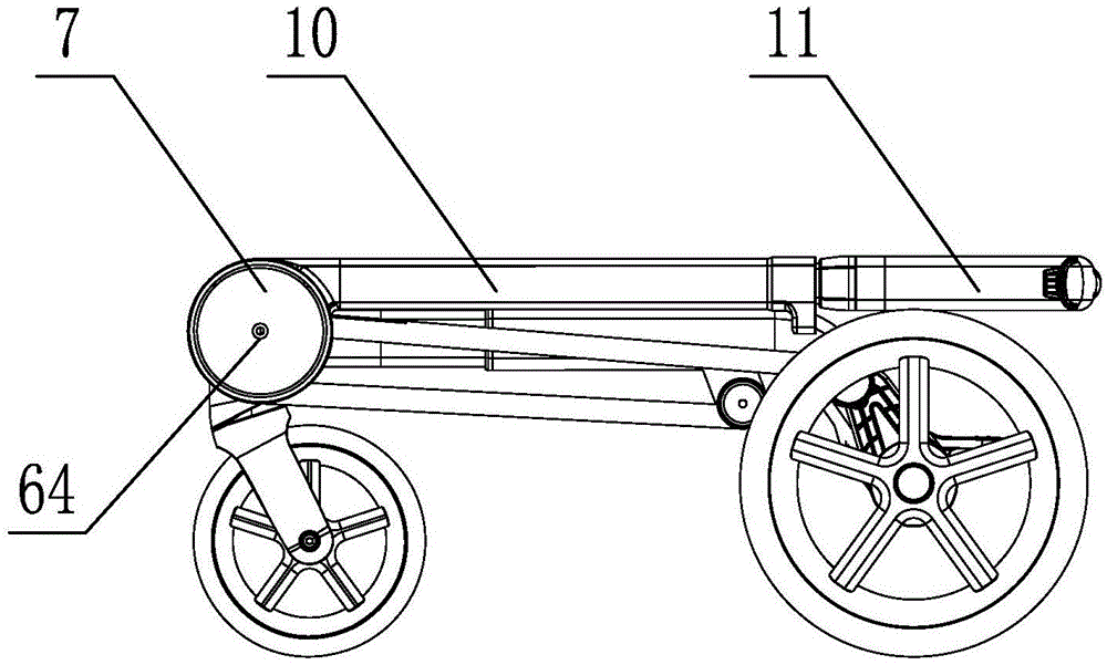
[0033] Such as Figure 4-6 As shown: the lower end of the lower push rod assembly 10 is connected with a push rod rotating part 100, the upper end of the front support rod assembly 2 is connected with a front support rod rotating part 20, and the upper end of the rear support rod assembly 3 is connected with a rear support rod rotating part 30, The push rod rotation member 100, the front support rod rotation member 20 and the rear support rod rotation member 30 are rotatably connected by a first shaft 64.
[0034] The linkage mechanism includes a first arc groove 60 opened on the push rod rotating part 100, a second arc groove 61 opened on the front support rod rotating part 20, a linear groove 62 opened on the rear support rod rotating part 30, and a sliding At block 63, the distance between the first arc-shaped groove 60 and the first shaft 64 gradually increases from top to bottom, and the distance between the second arc-shaped groove 61 and the first shaft 64 gradually decreases from top to bottom. The distance between the groove 62 and the first shaft 64 gradually decreases from top to bottom, and the sliding block 63 is provided with a shaft hole 630 and a sliding groove 631 extending along its length. The first shaft 64 passes through the sliding groove 631 of the sliding block 63; a second shaft 65 passes through the first arc-shaped groove 60, the second arc-shaped groove 61, the linear groove 62 and the shaft hole 630 of the sliding block 63 at the same time. The shaft 65 can slide in the first arc groove 60, the second arc groove 61, and the linear groove 62. When the push rod assembly 1 is pushed, the push rod rotating part 100 rotates, and the second shaft 64 in the first arc-shaped groove 60 slides. Driven by the sliding block 63, the second shaft 64 is in the linear groove of the rear support rod rotating part 30. 62. Synchronous sliding in the second arc-shaped groove 61 of the front support rod rotating member 20, thereby driving the front support rod assembly 2 and the rear support rod assembly 3 to rotate synchronously, realizing the linkage of rotation. The structure of the linkage mechanism is not limited to this, and any structure capable of realizing the linkage function can be used, which will not be repeated here.
[0035] In addition, the lower end of the push rod assembly 1, the upper end of the front strut assembly 2 and the upper end of the rear strut assembly 3 are provided with a rotating housing 7, and the linkage mechanism is arranged in the rotating housing 7.

PUM

no PUM

Description & Claims & Application Information

We can also present the details of the Description, Claims and Application information to help users get a comprehensive understanding of the technical details of the patent, such as background art, summary of invention, brief description of drawings, description of embodiments, and other original content. On the other hand, users can also determine the specific scope of protection of the technology through the list of claims; as well as understand the changes in the life cycle of the technology with the presentation of the patent timeline. Login to view more.

Similar technology patents

Body condition measuring device

InactiveUS20050234351A1simple structure
Owner:DENSO CORP

Magnetic cooling apparatus and control method thereof

ActiveUS20130180263A1simple structure
Owner:SAMSUNG ELECTRONICS CO LTD

Dual-Drivetrain of Power-Assist Vehicle

InactiveUS20100181130A1enhance uphill momentumsimple structure
Owner:CHOU WEN CHENG

Classification and recommendation of technical efficacy words

  • Simple structure
  • easy to operate

Sharing system for air-conditioning coat

InactiveCN107440179ASimple structureeasy to wear
Owner:QINGDAO HAIER AIR CONDITIONER GENERAL CORP LTD

Feeding device of sorter of batteries plate

InactiveCN101357717ASimple structurecooperate well
Owner:NANJING NORMAL UNIVERSITY

Emergency parachuting device and method for multiple-rotor unmanned aerial vehicle

InactiveCN103895870Aavoid aircraft crashSimple structure
Owner:SOUTH CHINA AGRI UNIV +1

Lancet device

InactiveUS7303573B2inexpensively mass-producedeasy to operate
Owner:ABBOTT DIABETES CARE INC

Rapid and non-invasive optical detection of internal bleeding

InactiveUS20050065436A1easy to operaterapid and accurate result
Owner:HO WINSTON ZONH +2
Why Eureka
Try Eureka