Pallets for Conveyor Belts

A conveyor belt and connecting rod technology, applied in the field of compressors, can solve the problems of wasting manpower, low efficiency, and difficult transmission of connecting rods, and achieve the effect of improving production efficiency and reducing waste of resources

Pending Publication Date: 2016-11-23
熊宝华
View PDF0 Cites 0 Cited by
  • Summary
  • Abstract
  • Description
  • Claims
  • Application Information

AI Technical Summary

Problems solved by technology

[0003] Compressor is a driven fluid machine that raises low-pressure gas to high-pressure. It is the heart of the refrigeration system. It sucks low-temperature and low-pressure refrigerant gas from the suction pipe, and drives the piston to compress it through the operation of the motor. The air pipe discharges high-temperature and high-pressure refrigerant gas to p

Method used


Image

  • Pallets for Conveyor Belts
  • Pallets for Conveyor Belts

Examples


Embodiment Construction

[0011] In order to deepen the understanding of the present invention, the present invention will be further described below in conjunction with the embodiments and accompanying drawings. The embodiments are only used to explain the present invention and do not constitute a limitation to the protection scope of the present invention.

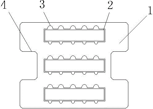
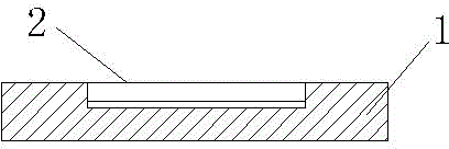
[0012] figure 1 An embodiment of a tray for a connecting rod conveyor belt of the present invention is shown, which includes a chassis 1 placed on the conveyor belt, a plurality of oil grooves 2 are provided on the chassis 1, and a number of oil grooves 2 are arranged in each oil groove 2. The parts groove 3 matched with the connecting rod, the depth of the oil groove 2 is greater than the depth of the parts groove 3; the two sides of the chassis 1 are provided with side grooves 4 embedded in the two sides of the conveyor belt; the chassis is provided with three oil grooves 2. There are five parts grooves 3 in each oil groove 2. Place the connect...


PUM


Abstract

The invention discloses a tray for a connecting rod conveyor belt, which includes a chassis placed on the conveyor belt, a plurality of oil grooves are arranged on the chassis, and a plurality of component grooves matching the connecting rod are arranged in each oil groove. The depth of the oil groove is greater than the depth of the part groove. The present invention adopts a tray placed on the conveyor belt, and the connecting rod is placed in the tray, which is convenient for the manipulator of the automatic feeding device to grab and place. At the same time, the oil groove on the tray can make the connecting rod After processing, the excess oil on the parts is filtered out, which not only plays the role of cleaning the parts, but also the oil in the oil tank can be added to the honing machine for recycling, which improves production efficiency and reduces waste of resources.

Description

technical field [0001] The invention relates to the field of compressors, in particular to a pallet for connecting rod conveyor belts used in the manufacture of compressors. [0002] Background technique [0003] Compressor is a driven fluid machine that raises low-pressure gas to high-pressure. It is the heart of the refrigeration system. It sucks low-temperature and low-pressure refrigerant gas from the suction pipe, and drives the piston to compress it through the operation of the motor. The air pipe discharges high-temperature and high-pressure refrigerant gas to provide power for the refrigeration cycle, thereby realizing the refrigeration cycle of compression→condensation→expansion→evaporation (heat absorption). Transported from the previous process, manual transport was used in the past, which was inefficient and wasted manpower, and it was not easy to put the connecting rod directly into the conveyor belt for transport. Contents of the invention [0004] In ord...

Claims


Application Information

Patent Timeline
IPC IPC(8): B65D1/36
Inventor 熊宝华
Owner 熊宝华
Why Eureka
Try Eureka