
Automatic bearing charging device

An automatic material feeding and material guiding device technology, applied in the direction of conveyor control device, support frame, transportation and packaging, etc., can solve the problem of high labor intensity of operators, monotonous and boring operation, and the failure to effectively guarantee the qualified rate of assembly, etc. problems, to achieve the effect of ensuring continuity and timeliness, improving reliability and stability, and avoiding untimely supply of materials

Inactive Publication Date: 2016-11-23
NINGBO DUNHE TECH CO LTD
View PDF6 Cites 37 Cited by
  • Summary
  • Abstract
  • Description
  • Claims
  • Application Information

AI Technical Summary

Problems solved by technology

[0003] Shaft parts usually need to be sleeved with bearings to achieve their role of rotational support. For example, during the assembly process of a motor, bearings need to be installed on the shafts on both sides of the rotor. The current rotor assembly line is manually assembled, that is, the installer manually places the bearings. Crimping the bearing on the bearing crimping seat, this method of feeding requires a lot of manpower, the long-term operation is monotonous and boring, the labor intensity of the operator is high, and the produced rotor is often due to manual pre-fitting of the bearing. The set is not correct, and the guide distance of the non-shaft end is too short, resulting in damage to the non-shaft end bearing after the bearing is press-fitted, the produced motor is noisy, the assembly qualification rate cannot be effectively guaranteed, and the amount of material loaded by the ordinary feeding method Less, the feeding device is complex, not suitable for mass production of products, labor-intensive and time-consuming, the efficiency is very low, and the production cost is very high

Method used


Image

  • Automatic bearing charging device
  • Automatic bearing charging device
  • Automatic bearing charging device

Examples


Embodiment Construction

[0031] In order to have a further understanding and understanding of the structural features of the present invention and the achieved effects, the preferred embodiments and accompanying drawings will be used for a detailed description, as follows:

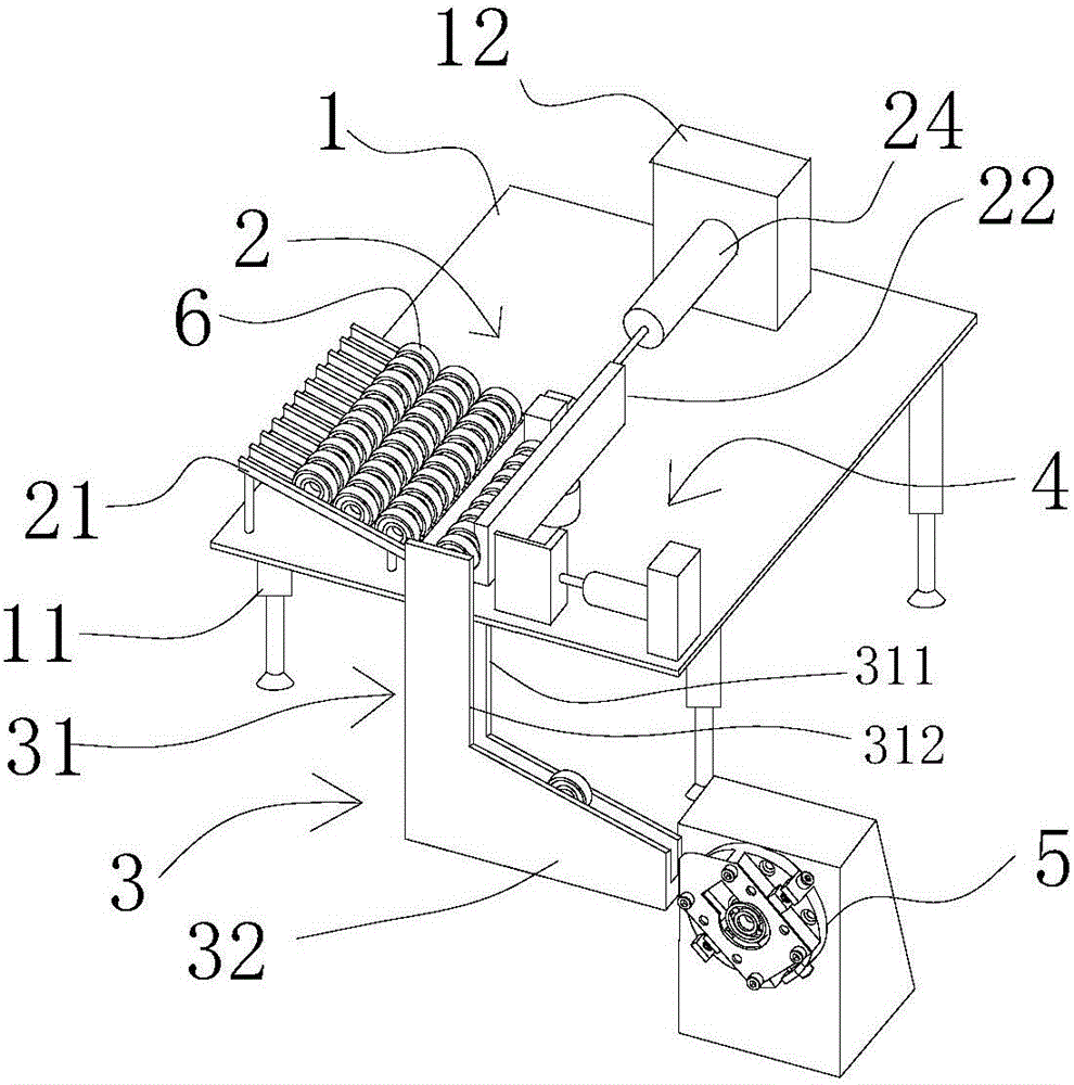
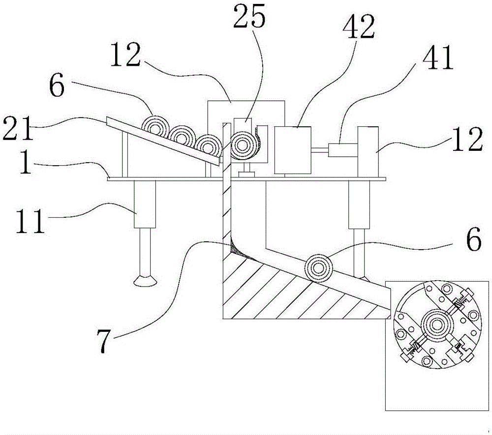
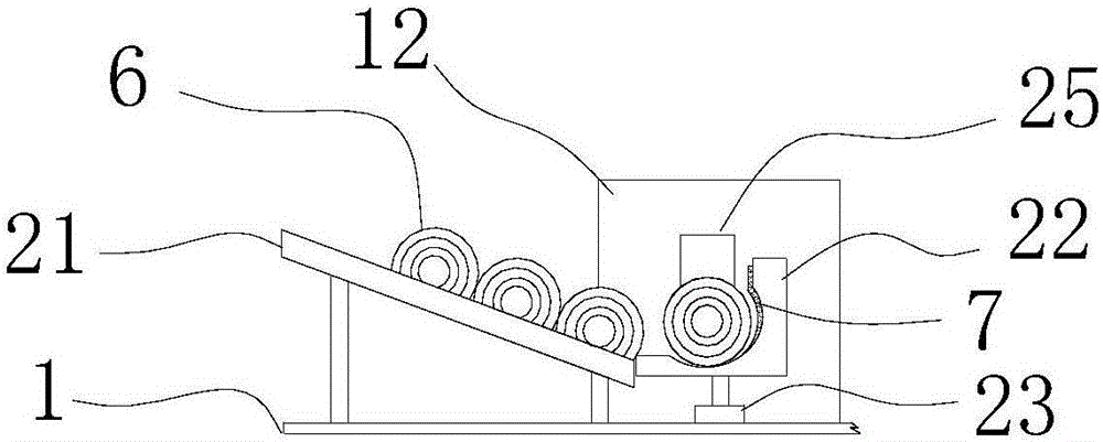
[0032] Such as figure 1 As described above, an automatic bearing feeding device, as an improvement of the present invention, includes a support platform 1, a material guide device 2 arranged on the support platform 1, and a guide device 3 arranged on the side of the support platform 1 on the side of the material guide device 2 , the material stopper 4 that is arranged between the guide device 2 and the guide device 3, the bearing crimping seat 5 that is connected with the lower end of the guide device 3, the material guide device 2 is provided with a code rack 21 with an included angle relative to the horizontal plane, The pusher baffle 22 that is L-shaped at the bottom of the code rack 21, the lifting cylinder 23 that is arranged...


PUM


Abstract

The invention relates to the field of rotor press mounting bearings, and provides an automatic bearing charging device. The automatic bearing charging device comprises a support table, a material guide device, a guiding device, a material blocking device and a bearing press connection seat; the material guide device is arranged on the support table; the guiding device is arranged on one side, located at the material guide device, of the support table; the material blocking device is arranged between the material guide device and the guiding device; the bearing press connection seat is connected with the lower end of the guiding device; the material guide device consists of a material stacking rack, a material pushing baffle, a lifting air cylinder, a material pushing air cylinder and a material pushing block; an included angle is formed between the material stacking rack and the horizontal plane; the material pushing baffle is arranged at the bottom end of the material stacking rack and is L-shaped; the lifting air cylinder is arranged at the bottom of the material pushing baffle; the material pushing air cylinder is arranged at one end of the material pushing baffle; and the material pushing block is fixedly connected with the free end of a piston rod of the material pushing air cylinder and is located above the material pushing baffle. The automatic bearing charging device can realize the effect of automatically charging bearings in batches, is convenient to use and operate and high in efficiency, and is suitable for large-scale popularization.

Description

technical field [0001] The invention relates to the field of rotor press-mounted bearings, in particular to an automatic bearing feeding device. Background technique [0002] Mechanical automation technology is an advanced technology in the machinery manufacturing industry. Applying mechanical automation technology to all aspects of machinery manufacturing can effectively improve the production capacity of machinery manufacturing and improve the economic benefits of enterprises. The application of mechanical automation reflects the manufacturing level of a country's mechanical equipment. Through actual analysis, research on the development prospects of mechanical automation can determine the development direction of my country's machinery manufacturing industry and ensure that my country's machinery manufacturing technology is in line with international standards. [0003] Shaft parts usually need to be sleeved with bearings to achieve their role of rotational support. For ...

Claims


Application Information

Patent Timeline
IPC IPC(8): B65G47/29B65G41/00B65G47/22B65G47/82B65G43/08B65G11/08B23P19/00B23P19/02
CPCB65G47/29B23P19/001B23P19/02B65G11/081B65G41/003B65G43/08B65G47/22B65G47/82B65G2201/0214B65G2203/042
Inventor 姜飒赵艳黄兆伟姜亚俊
Owner NINGBO DUNHE TECH CO LTD
Features
  • Generate Ideas
  • Intellectual Property
  • Life Sciences
  • Materials
  • Tech Scout
  • Unparalleled Data Quality
  • Higher Quality Content
  • 60% Fewer Hallucinations
Learn More