[0033] The preferred embodiments of the present invention will be described in detail below in conjunction with the accompanying drawings, so that the advantages and features of the present invention can be more easily understood by those skilled in the art, so as to define the protection scope of the present invention more clearly.
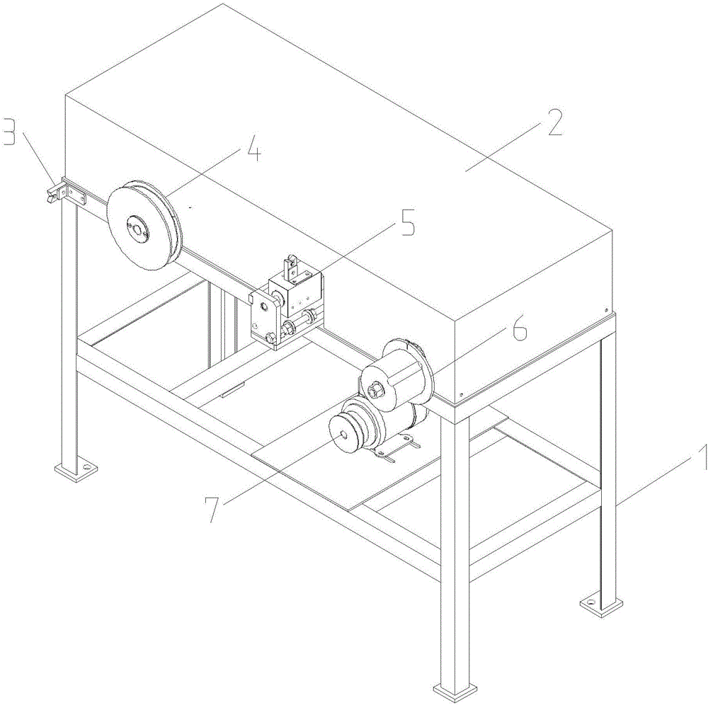
[0034] refer to figure 1 As shown, the present invention provides a coiling device, comprising the following components:
[0035] A first wire mechanism 3, used to guide the wire to be coiled;
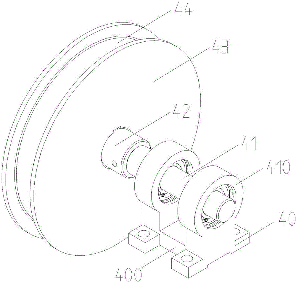
[0036] A meter counting component 4, used for counting the wire to be coiled;
[0037] A wire arranging device 5 for arranging the wires to be coiled;
[0038] A reel assembly 6, used to reel the wire to be reeled;
[0039] And a power assembly 7, used to drive the action of the cable unwinder 5 and the winding wheel assembly 6;
[0040] The first wire mechanism 3 , the meter counting assembly 4 , the cable guide 5 and the winding wheel assembly 6 are sequentially arranged.
[0041] Through the above-mentioned setting of the present invention, on the one hand, because the first wire mechanism 3 can guide the coiled wire, when coiling the wire, the line can be moved more accurately, so as to avoid the influence of the wire on the coiled wire due to the effect of gravity, and make the coiled wire The guideline of the wire is better. On the other hand, the power assembly 7 is used to replace the manual winding, which greatly improves the efficiency and reduces the labor intensity. On the other hand, the back and forth movement of the wire arranging device 5 can make the wire more uniform. Coil the wire on the coiling wheel assembly 6.
[0042] refer to figure 1 , figure 2 and Figure 11 As shown, the present invention also includes a frame 1 and a shield 2, the frame 1 includes a leg 14, a panel 15 arranged at the upper end of the leg 14, and a bracket arranged at the middle of the leg 14 Layer 11, the first wire mechanism 3, the meter assembly 4, the cable arrangement 5 and the coil wheel assembly 6 are installed on the panel 15 in sequence, and the power assembly 7 is installed on the support layer 11; The shield 2 is mounted on the panel 15.
[0043] The present invention also sets openings on the end face of the shield 2 corresponding to the meter counting assembly 4 , the wire deflector 5 and the winding wheel assembly 6 .
[0044] The present invention is also provided with the through groove 16 that matches with the first main shaft pulley 62 and the second main shaft pulley 63 on the surface of the panel 15, so as to pass through the normal operation of the first main shaft pulley 62 and the second main shaft pulley 63. rotation, and the belt connection between the first main shaft pulley 62 and the power pulley 12 .
[0045] In the present invention, a fixing plate 17 for installing the power assembly 7 is also provided on the support layer 11 , and a support pad 13 is also installed at the bottom of the supporting leg 14 .
[0046] refer to Figure 3-Figure 5 As shown, the meter counting assembly 4 in the present invention includes a bearing seat 40, a meter counting wheel shaft 41, an axle sleeve 42, a meter counting wheel 43 and a bearing 46, and one end of the meter counting wheel shaft 41 is installed on the bearing through a bearing 46 On the seat 40, the bearing seat 40 is installed on the frame 1, and the meter counting wheel 43 is fixedly installed on the other end of the meter counting wheel shaft 41, and the meter counting wheel 43 extends to the frame 1. The outer side, and the outer side of the meter wheel 43 is provided with a guide ring groove 44 .
[0047] During specific processing, a disk-shaped structure is arranged on the outside of the axle sleeve 42, and the disk-shaped structure is connected with the outside of the meter counting wheel 43 by the first fastener 48, and is arranged on the outside of the axle sleeve 42 and the inside of the meter counting wheel 43. The keyway 47 connects the axle sleeve 42 and the meter wheel 43 through the key 45 .
[0048] The bearing seat 40 includes a base 400 and two bearing sleeves 410 integrally installed on the base 400 , there is a space between the two bearing sleeves 410 , so that the meter wheel shaft 41 is installed in the bearing sleeves 410 through two bearings 46 .
[0049] refer to Image 6 and Figure 7 As shown, the cable arrangement 5 in the present invention includes a base plate 50, a cable arrangement body 51 and a second wire mechanism, the cable arrangement body 51 is mounted on the bottom plate 50, and the second wire mechanism is installed on On the cable straightener body 51 .
[0050]Specifically, the first wire mechanism 3 and the second wire mechanism have the same structure, and both include a wire nozzle 53 and a wire nozzle bracket. The wire nozzle 53 is provided with a wire hole 56, and the upper end of the wire nozzle 53 is provided with a The twisted groove 57 communicated with the wire hole 56, the twisted groove 57 extends to the outside of the wire nozzle 53, the wire nozzle 53 of the first wire mechanism 3 is installed on the frame 1 through the wire nozzle bracket, so The wire nipple 53 of the above-mentioned second wire mechanism is installed on the wire arranging device body 51 through the wire nipple bracket.
[0051] Due to the twisted structure of the twisted groove 57, compared with the direct setting of the guide hole, on the one hand, it is convenient for threading and adjustment of the thread (for example, the thread is twisted and needs to be re-threaded), and on the other hand, it can also prevent the thread from occurring during the coiling process. fall off.
[0052] Wherein, the first L-shaped connector 8 is used as the wire tip holder of the first wire mechanism 3, the third L-shaped connector 52 is used as the wire nozzle bracket of the second wire mechanism, and the wire nozzle of the first wire mechanism 3 53 is horizontally installed on the outside of the frame 1 through the first L-shaped connector 8, and the wire nipple 53 of the second wire mechanism is vertically installed on the frame 1 through the third L-shaped connector 52.
[0053] In order to facilitate the winding of lines of different types, a distance adjustment mechanism is also provided between the wire nozzle 53 and the wire nozzle bracket, and the distance adjustment mechanism includes a lifting groove 54 arranged on the wire nozzle 53, and fasteners 55 , the fastener 55 is fixedly connected to the wire nozzle bracket and the lifting slot 54 . By adjusting the fastener 55, the wire nozzle 53 of the first wire mechanism 3 can be adjusted in lateral displacement, and the wire nozzle 53 of the second wire mechanism can be adjusted in vertical displacement.
[0054] refer to Figure 8 and Figure 9 As shown, the coiling wheel assembly 6 includes a main shaft 65, a bearing 66 and a coiling wheel 67, the bearing 66 is installed in the middle of the main shaft 65, and the coiling wheel 67 (the inside of which is provided with a baffle 71) is installed At one end of the main shaft 65 and the coil wheel 67 extends to the outside of the frame 1, the other end of the main shaft 65 is connected with the power end of the power assembly 7 through the first belt transmission mechanism, and the other end of the main shaft 65 It is also connected with the cable puller 5 through the second belt transmission mechanism.
[0055] The first belt transmission mechanism includes a power pulley 12, a first main shaft pulley 62 and a first transmission belt, the power pulley 12 is installed on the output end of the power assembly 7, and the first main shaft pulley 62 is installed on On the main shaft 65 , the first transmission belt connects the power pulley 12 and the first main shaft pulley 62 .
[0056] The second belt drive mechanism includes a cable pulley 10, a second main shaft pulley 63 and a second transmission belt, the cable pulley 10 is installed on the input shaft of the cable pulley 5, and the second main shaft The pulley 63 is installed on the main shaft 65 , and the second transmission belt connects the cable pulley 10 and the second main shaft pulley 63 .
[0057] Specifically, the first main shaft pulley 62 , the second main shaft pulley 63 , the bearing 66 and the winding wheel 67 are sequentially arranged on the main shaft 65 , and the first main shaft pulley 62 passes through the fastener 60 and the gland 61 Fixed, the coiling wheel 67 is fixed on the end of the main shaft 65 through a washer 69 and a nut 70 .
[0058] The first main shaft pulley 62 and the second main shaft pulley 63 are connected to the main shaft 65 through a key 64 , and the winding wheel 67 is connected to the main shaft 65 through a key 68 .
[0059] Figure 9 A pin is inserted into the middle elastic groove 72. When the coiling is completed, the pin is taken out first to facilitate the removal of the entire coiled wire from the coiling wheel 67. The threading knife 73 strokes the tail of the thread removed from the coiling wheel 67. .
[0060] Preferably, the power assembly 7 is a motor, that is, the power pulley 12 is installed on the output shaft of the motor.
[0061] refer to Figure 10 As shown, the coil wheel 67 in the present invention can be replaced by a cable wheel body, and the cable wheel body includes a cable wheel sleeve 74, a first wire retaining plate 75 and a second wire retaining plate 76. The first line retaining plate 75 and the second line retaining plate 76 are respectively arranged at both ends of the cable sheave 74 , and the cable sheave 74 is sleeved on the main shaft 65 . A plurality of radial grooves 77 are arranged on the second wire retaining plate 76, which is convenient for observing the thickness of the coil wire.
[0062] The coiling method principle of the coiling device of the present invention is:
[0063] First, pass the wire to be coiled sequentially through the wire nozzle 53 of the first wire mechanism 3, the meter counting wheel 43 of the meter counting assembly 4, the wire nozzle 53 on the wire arranging device 5 and the coiling wheel on the coiling wheel assembly 6 67;
[0064] Then, start the power assembly 7 (i.e. motor), the motor drives the main shaft of the reel wheel assembly 6 to rotate through the first belt drive mechanism, and the main shaft drives the cable puller 5 to rotate through the second belt drive mechanism, and the cable puller 5 Driven back and forth, the coiled wire is evenly coiled on the coil wheel 67 of the coil wheel assembly 6.
[0065] Although the embodiments of the present invention have been described in conjunction with the accompanying drawings, the patent owner can make various deformations or modifications within the scope of the appended claims, as long as they do not exceed the scope of protection described in the claims of the present invention, all should Within the protection scope of the present invention.