Lifting mechanism for fruit box stacking
A technology for stacking and fruit, applied in the field of lifting mechanism for stacking fruit boxes, can solve the problems of affecting cutting quality, poor lifting stability, small contact area, etc., and achieve the effect of improving cutting quality, stable lifting and small shaking amplitude.
- Summary
- Abstract
- Description
- Claims
- Application Information
AI Technical Summary
Problems solved by technology
Method used
Image
Examples
Embodiment 1
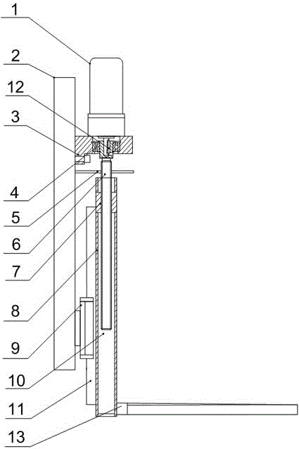
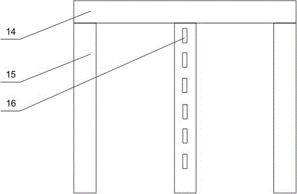
[0022] Such as figure 1 and figure 2 As shown, this includes a fixed plate 2, the fixed plate 2 is installed on the cutting machine, a mounting seat 3 is arranged on the upper end of the fixed plate 2, a motor 1 is arranged on the mounting seat 3, and a linear guide rail is installed at the lower end of the fixed plate 2 11 pairs, the 11 pairs of linear guide rails are connected with a lifting column 8, and a blind hole 10 is opened on the lifting column 8, and also include a lifting screw 6 and a nut 7, and the nut 7 is fixed in the blind hole 10, and the lifting screw 6 One end passes through the nut 7 and is placed in the blind hole 10, the other end of the lifting screw 6 passes through the mounting base 3 and is connected to the output end of the motor 1, and the lifting screw 6 can rotate freely in the mounting base 3 on the lifting column 8. A front fork 13 is installed on the side wall. The front fork 13 is composed of a support rod 14 and three legs 15 arranged side...
Embodiment 2
[0027] Such as figure 1 As shown, in this embodiment, on the basis of Embodiment 1, the linear guide rail 11 pair includes a linear guide rail 11 and a slider 9, and the linear guide rail 11 is arranged on the outer wall of the lifting column 8 close to the fixed plate 2 side, so The slider 9 is fixedly installed on the lower end of the fixed plate 2, and the linear guide rail 11 is slidably arranged on the slider 9. In order to improve the lifting stability of the lifting mechanism, the weight of the installation parts is light and the shaking is serious when the lifting column 8 is lowered to a low position, on the basis of the original transmission mode, the slider 9 of the linear guide rail 11 and the linear guide rail 11 are mutually connected. Change the position, that is, the slider 9 is installed on the fixed plate 2, and the linear guide rail 11 is fixed on the lifting column 8, because the length of the linear guide rail 11 is much longer than that of the slider 9, t...
Embodiment 3
[0029] Such as figure 1 As shown, on the basis of Embodiment 1, the present embodiment is provided with a bearing 4 inside the mounting seat 3, and the lifting screw 6 passes through the bearing 4, and the upper end of the lifting screw 6 has a mounting hole, and the motor 1 The output end is fixed in the installation hole through the flat key 12; it also includes a limit plate 5, the limit plate 5 is installed on the fixed plate 2, and a through hole is opened on the limit plate 5, and the lifting screw rod 6 passes through the through hole. The inner diameter of the through hole is smaller than the outer diameter of the nut 7. The bearing 4 can make the lifting screw 6 reduce the radial vibration of the lifting screw 6 when the motor 1 is just started or turned off or suddenly changes speed, so as to ensure the stability of the lifting screw 6; , the connection between the output end of the motor 1 and the lifting screw 6 is prone to loosening, and the output end of the mot...
PUM
 Abstract
Description
Claims
Application Information
 - R&D
- Intellectual Property
- Life Sciences
- Materials
- Tech Scout
- Unparalleled Data Quality
- Higher Quality Content
- 60% Fewer Hallucinations
Browse by: Latest US Patents, China's latest patents, Technical Efficacy Thesaurus, Application Domain, Technology Topic, Popular Technical Reports.
© 2025 PatSnap. All rights reserved.Legal|Privacy policy|Modern Slavery Act Transparency Statement|Sitemap|About US| Contact US: help@patsnap.com


