Equipment for conveying glass plates on air bearing table in heating furnace

A technology of supporting table and heating furnace, applied in glass manufacturing equipment, glass transportation equipment, manufacturing tools, etc.

Inactive Publication Date: 2016-11-23
GLASTON FINLAND
View PDF3 Cites 2 Cited by
  • Summary
  • Abstract
  • Description
  • Claims
  • Application Information

AI Technical Summary

Problems solved by technology

Therefore there is no sp

Method used


Image

  • Equipment for conveying glass plates on air bearing table in heating furnace
  • Equipment for conveying glass plates on air bearing table in heating furnace
  • Equipment for conveying glass plates on air bearing table in heating furnace

Examples


example 1

[0052] Example 1: No glass on air bearing (0% load).

[0053] In the apparatus according to the invention, the suction side of the blower is 3 x A free hole area to the furnace.

[0054] In the device according to publication US 8 297 077, the suction side of the blower has a free hole area of ​​1.125×A leading to the furnace.

example 2

[0055] Example 2: The air bearing table is half covered with glass (loading degree 50%).

[0056] In the apparatus according to the invention, the suction side of the blower is a free hole area of ​​2.5×A+C×0.5×A to the furnace.

[0057] In the device according to publication US 8 297 077, the suction side of the blower is a free hole area of ​​0.625×ΣA+C×0.5×A to the furnace.

example 3

[0058] Example 3: The air bearing table is fully covered with glass (100% loading).

[0059] In the apparatus according to the invention, the suction side of the blower is a free hole area of ​​2*A+C*A to the furnace.

[0060] In the device according to publication US 8 297 077, the suction side of the blower is a free hole area of ​​0.125×A+C×A leading to the furnace.

[0061] In the above, the coefficient C defines how large the proportion of free vent holes is to the vent holes below the glass. The coefficient C depends on the variation of the most confined surface area of ​​the vent hole, which follows the calculations below.

[0062] The surface area of ​​the mouth of the free vent hole is (п / 4)D 2 , where D is the diameter of the mouth of the exhaust hole. The diameter of the mouth of the vent hole held below the glass is пDH, where H is the height of the air bed. A typical height H of the air bed is 0.5 mm and the diameter of the exhaust opening is 10 mm. Therefore...


PUM


Abstract

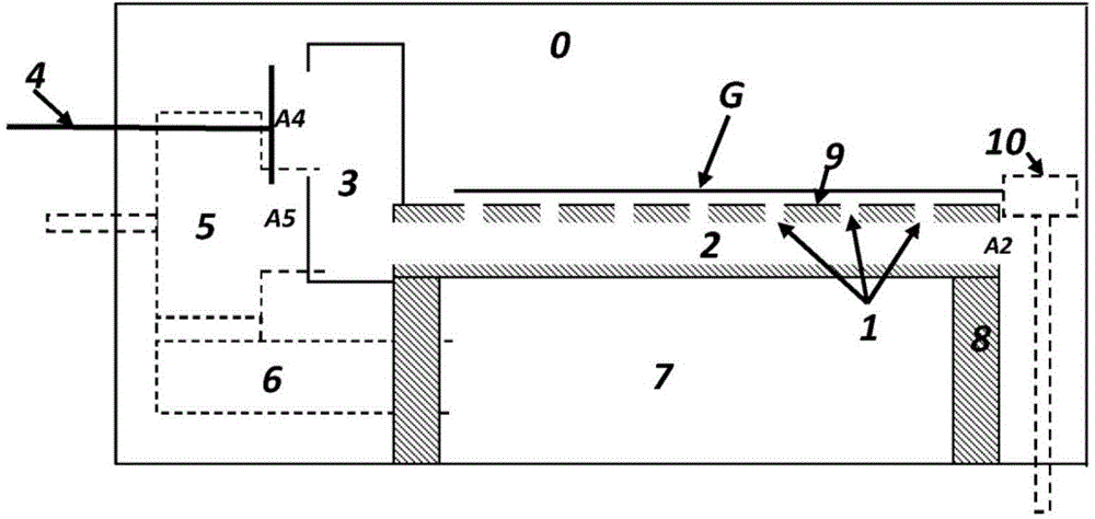
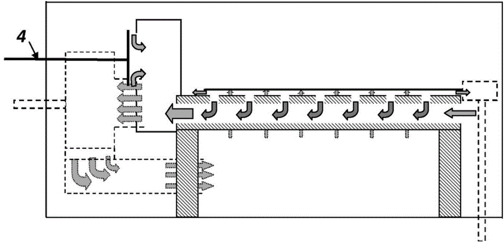
The invention provides equipment for conveying glass plates on an air bearing table (9) in a heating furnace. The air bearing table comprises air supply holes (12) and air exhaust holes (1). The air supply holes are connected to a pumping chamber (7) below the air bearing table (9), the air exhaust holes (1) are connected to an air exhaust channel (2) in the air bearing table, and the first end of the air exhaust channel is led into the heating furnace (0) or provided with a sealed gate valve (13) capable of being switched off and switched on. The second end of the air exhaust channel (2) is led to a suction pipeline (3) or provided with a blocking gate valve (11) capable of being switched off and switched on. The suction pipeline (3) of an air blower is located on the side, opposite to a conveyor (10), of the air bearing table (9), and the conveyor makes contact with glass. At least one adjustable bypass gate valve (4) for adjusting air bearing of the glass is arranged in the suction pipeline (3) between the air exhaust channel (2) and the air blower (5).

Description

technical field [0001] The invention relates to an apparatus for conveying glass sheets on an air bearing table in a heating furnace, the top surface of which is arranged to form an inclination of 0-20° with respect to the horizontal plane, said apparatus being at the edge of the air bearing table A transfer roller is included, wherein the top surface of the air bearing table slopes toward the edge. A horizontal arrangement of the air bearing table is also feasible if the conveyor rollers are replaced by conveyors in contact with the glass. In an air-supported furnace, the glass is heated to tempering temperature. The air bearing includes air supply holes and exhaust holes. The air flowing through the air supply holes under the glass generates an overpressure under the glass relative to the pressure prevailing in the furnace, on the basis of which the glass floats on the air bed. The overpressure of the supporting glass reaches its peak at the pressure port. The vent preve...

Claims


Application Information

Patent Timeline
IPC IPC(8): C03B35/24
Inventor M·兰塔拉H·屈尔韦耶J·韦赫马斯K·凯托
Owner GLASTON FINLAND
Why Eureka
Try Eureka