Automatic drainage system for hydraulic engineering construction as well as manufacture method and application method of automatic drainage system

A technology for automatic drainage and water conservancy projects, applied in waterway systems, drainage structures, water supply devices, etc., can solve problems such as difficulty in satisfying construction personnel and the market, failure to form a drainage system, delay in construction progress, etc., and achieve simple structure and improved Water collection efficiency, vibration reduction effect

Inactive Publication Date: 2016-11-23
李明
View PDF6 Cites 2 Cited by
  • Summary
  • Abstract
  • Description
  • Claims
  • Application Information

AI Technical Summary

Problems solved by technology

[0002] At present, the structure of the traditional drainage device is simple, but it does not constitute a certain drainage system, the degree of automation is low, the drainage efficiency is low, and the effect is not obvious. The progress of construction is delayed, and it is difficult to meet the needs of construction personnel and the market

Method used


Image

  • Automatic drainage system for hydraulic engineering construction as well as manufacture method and application method of automatic drainage system
  • Automatic drainage system for hydraulic engineering construction as well as manufacture method and application method of automatic drainage system
  • Automatic drainage system for hydraulic engineering construction as well as manufacture method and application method of automatic drainage system

Examples


Embodiment Construction

[0015] The following will clearly and completely describe the technical solutions in the embodiments of the present invention with reference to the accompanying drawings in the embodiments of the present invention. Obviously, the described embodiments are only some, not all, embodiments of the present invention. Based on the embodiments of the present invention, all other embodiments obtained by persons of ordinary skill in the art without making creative efforts belong to the protection scope of the present invention.

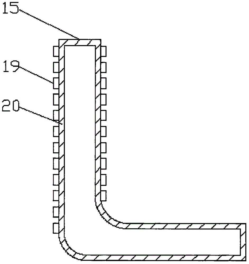
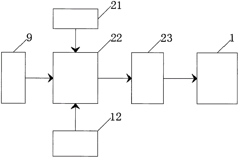
[0016] see Figure 1-3 , an embodiment provided by the present invention: an automatic drainage system for water conservancy construction and its manufacture and use method, including a water pump 6 and a water storage device 11, the water pump 6 and the motor 1 pass through the driving shaft 2, the coupling 3 and the driven The shaft 17 is rotatably connected, and the coupling 3 is fixed between the driving shaft 2 and the driven shaft 17. The motor 1 and the...


PUM


Abstract

The invention discloses an automatic drainage system for hydraulic engineering construction as well as a manufacture method and an application method of the automatic drainage system. The automatic drainage system comprises a water pump and a water accumulation device, wherein the water pump is rotationally connected with a motor through a driving shaft, a coupling and a driven shaft; the coupling is fixed between the driving shaft and the driven shaft; the motor and the water pump are fixed on a base; a water outlet is formed in the upper end of the water pump, and a water suction port is formed in the right end of the water pump and fixedly connected with a pipeline through fixing bolts; a flow sensor is mounted on the pipeline and is in sealing connection with a water collector through the pipeline; the left end and the right end of the water collector are in sealing connection with water collection pipes; a water collection chamber is formed in the water collector, a water suction pipe and a liquid level sensor are mounted in the water collection chamber, and the liquid level sensor is mounted on the water suction pipe. The flow sensor and the liquid level sensor of the automatic drainage system are matched for use, so that full-automatic drainage can be realized, and the working efficiency can be increased.

Description

technical field [0001] The invention relates to the technical field of drainage devices, in particular to an automatic drainage system for water conservancy construction and methods for manufacturing and using the same. Background technique [0002] At present, the structure of the traditional drainage device is simple, but it does not constitute a certain drainage system, the degree of automation is low, the drainage efficiency is low, and the effect is not obvious. The progress of construction is delayed, and it is difficult to meet the needs of construction personnel and the market. Contents of the invention [0003] The purpose of the present invention is to provide an automatic drainage system for water conservancy construction and its manufacture and use method, to solve the problems raised in the above-mentioned background technology, the beneficial effect is: the cooperative use of flow sensing device and liquid level sensing device can Realize automatic drainage ...

Claims


Application Information

Patent Timeline
Patent Type & Authority Applications(China)
IPC IPC(8): E03F5/22F04D13/06
CPCE03F5/22F04D13/06
Inventor 李明赵严华张伟
Owner 李明
Why Eureka
Try Eureka