Sliding guide mechanism for bathroom

A sliding guide, bath room technology, applied in the field of bath room and bathroom facilities, can solve the problems of poor anti-swing effect, easy damage, wear, etc., and achieve the effect of improving smoothness, reducing lateral swing, and not easy to wear

Inactive Publication Date: 2016-11-23
中山市雅润卫浴有限公司
View PDF7 Cites 3 Cited by
  • Summary
  • Abstract
  • Description
  • Claims
  • Application Information

AI Technical Summary

Problems solved by technology

[0003] The guide mechanism of the existing shower room is relatively simple, only the base is made into an "L" shape, and the front and rear swing of the shower room door is limited by the contact between the longitudinal part of the base and the bottom side of the door. Hook the hanging piece, and set the corresponding hooking groove on the base, hang the hooking piece in the hooking groove, and also use the abutment of the side wall of the hooking piece and the inner wall of the hooking groove to limit the front and rear swing of the shower room door, In these guide mechanisms, due to the friction between the fittings during the sliding opening and closing process of the door, it will affect the sliding smoothness of the door, and it is easy to wear and damage after long-term use. Moreover, in order to To prevent the sliding of the door from being hindered, there is usually a large gap between the fittings, so the anti-swing effect is poor

Method used


Image

  • Sliding guide mechanism for bathroom
  • Sliding guide mechanism for bathroom
  • Sliding guide mechanism for bathroom

Examples


Embodiment Construction

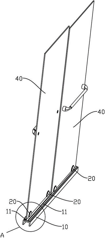
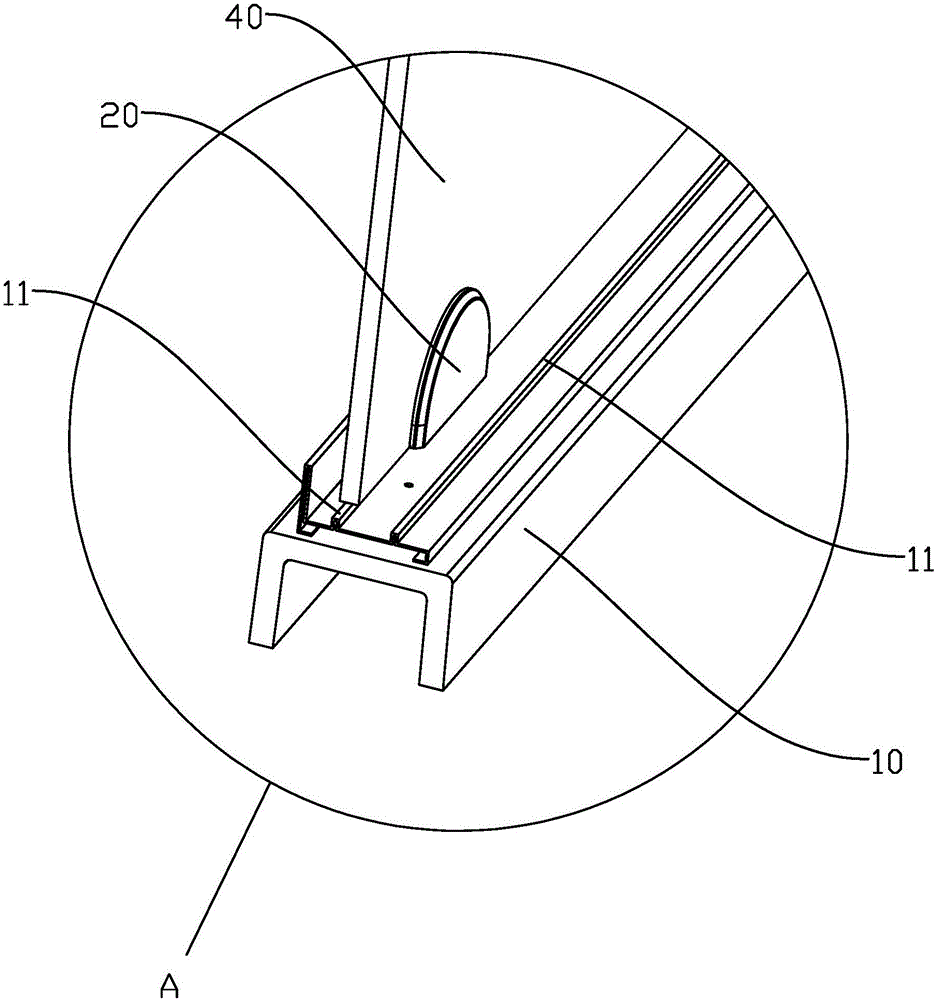
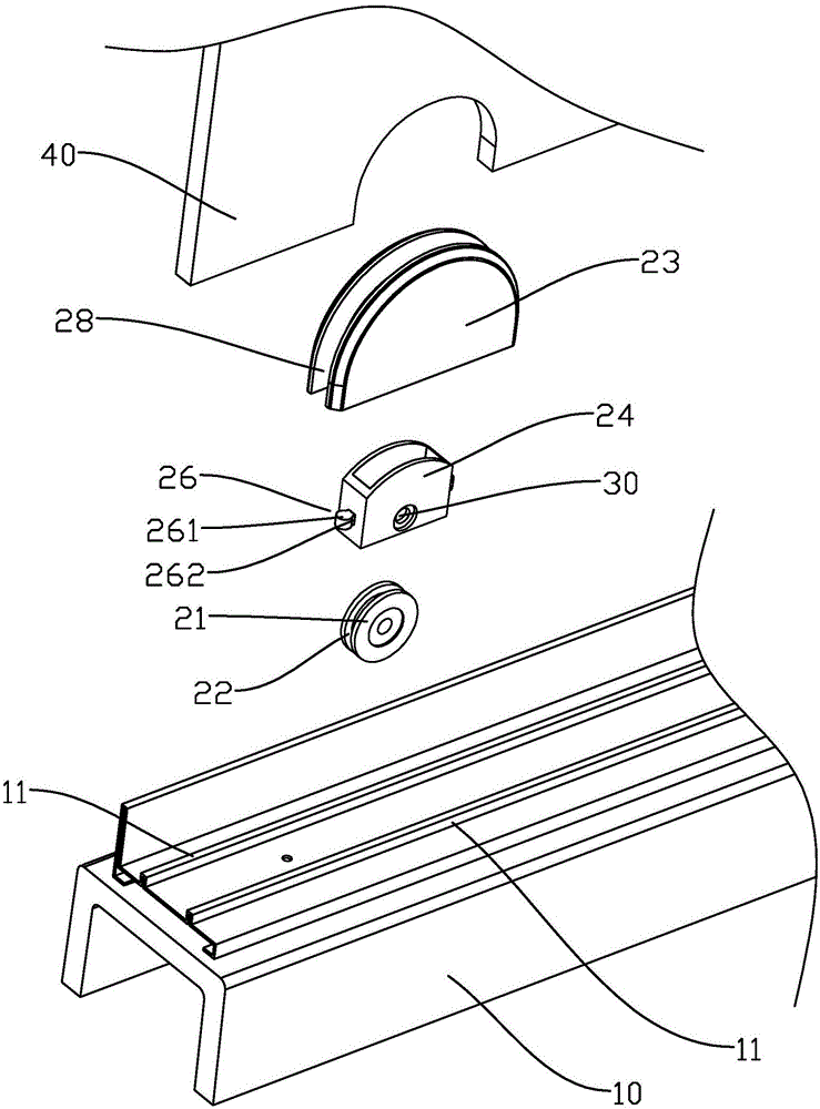
[0022] refer to Figure 1 to Figure 4 , a sliding guide mechanism for a shower room, including a base 10 and at least one mounting seat 20 that can be installed on the door 40, the mounting seat 20 has at least one clamping groove 28, the door 40 can be embedded in the clamping In the groove 28, it is convenient to connect the mounting seat 20 with the door 40. A roller 21 is pivotally arranged on the mounting seat 20 through a horizontal pivot shaft 30. The base 10 has a first stopper, and the roller 21 is pivotally connected The shaft 30 is provided with a second limiting portion, wherein, one of the first limiting portion and the second limiting portion is a longitudinal limiting groove 22, and the other is a longitudinal limiting protrusion adapted to the groove. Lifting 11, the position-limiting protrusion 11 is longitudinally inserted into the position-limiting groove 22, and the two outer walls of the position-limiting protrusion 11 are respectively close to or close to...


PUM


Abstract

The invention discloses a sliding guide mechanism for a bathroom. The sliding guide mechanism comprises a base and at least one mounting base mounted on a door, wherein an idler wheel is pivoted on the mounting base through a horizontal pivot shaft; a first limiting part is arranged on the base; a second limiting part is arranged on the idler wheel around the pivot shaft; one of the first limiting part and the second limiting part is arranged as a longitudinal limiting groove and the other is arranged as a longitudinal limiting bulge matched with the groove; the limiting bulge is longitudinally inserted into the limiting groove; two outer side walls of the limiting bulge are respectively clung to or close to the two inner side walls of the limiting groove. The sliding guide mechanism for the bathroom can effectively reduce the resistance ensured by the door in a sliding process, so that the sliding smoothness of the door is effectively increased and the door is difficult to be worn. The outer side walls of the limiting bulge are respectively clung to or close to the two inner side walls of the limiting groove, so that the lateral swinging of the door relative to the base can be effectively reduced.

Description

technical field [0001] The invention relates to the field of bathroom facilities, in particular to the field of shower rooms. Background technique [0002] The shower room can isolate a relatively independent bathing space in the bathroom, and has many advantages such as easy cleaning, cleanliness and sanitation. With the improvement of people's living standards, the shower room has been more and more widely used in people's home life. In order to save space and facilitate the opening and closing of the cabinet door, the doors of most shower rooms usually adopt a push-pull structure. In order to prevent the shower door from swinging back and forth, a guiding mechanism needs to be set between the door and the frame. [0003] The guide mechanism of the existing shower room is relatively simple, only the base is made into an "L" shape, and the front and rear swing of the shower room door is limited by the contact between the longitudinal part of the base and the bottom side of ...

Claims


Application Information

Patent Timeline
Patent Type & Authority Applications(China)
IPC IPC(8): E05D15/06
CPCE05D15/0656E05D15/0621
Inventor 李岳刚王会芳
Owner 中山市雅润卫浴有限公司
Why Eureka
Try Eureka