
Driving mechanism for outward sliding vehicle door

A driving mechanism and sliding door technology, applied in the direction of power control mechanism, wing leaf control mechanism, door/window accessories, etc., can solve the problems of limited life, complex structure, limited service life, etc., to reduce bloat and simple technology , the effect that is not easy to arrange

Pending Publication Date: 2016-11-23
曾锦丽
View PDF10 Cites 1 Cited by
  • Summary
  • Abstract
  • Description
  • Claims
  • Application Information

AI Technical Summary

Problems solved by technology

The inner swing door itself is not sealed from the design structure, occupies the passage space, has the risk of injury to the occupants, and the interior layout is not beautiful, while the outer sliding door is most suitable for use on large-capacity buses; the outer sliding door The existing patented scheme (200620025131 passenger car door external sliding door machine system; 200520024867.7 passenger car door automatic sliding device) and the currently used external sliding door drive mechanism have a swing mechanism and an up and down mechanism in addition to slideways and roller trolleys. Synchronous mechanism, so the structure is complex and expensive, and it is not easy to be transplanted to the bus. So far, no outer sliding door has been used on the bus; while the transmission part of the outer sliding door structure used on the car has a sheave type, and the rope The service life of the wheel type is limited. The life standard of the door switch of a car is 100,000 times, and the life standard of the door switch of a bus and rail train is 500,000 to 1 million times. The thin steel wire rope of the car sheave type drives the door to run to the corner. Runs frictionally against the slideway, so life is more limited

Method used


Image

  • Driving mechanism for outward sliding vehicle door
  • Driving mechanism for outward sliding vehicle door
  • Driving mechanism for outward sliding vehicle door

Examples


Embodiment Construction

[0012] Take the implementation of the single-leaf outer sliding door of a bus as an example:

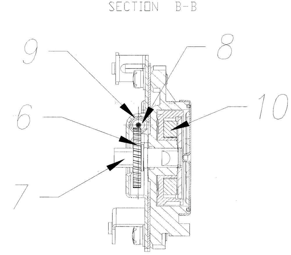
[0013] Such as figure 1 , figure 2 , image 3 As shown, the outer sliding door is restrained on the vehicle body through the upper, middle and lower three arc-shaped slides through the sliding door connector and each roller trolley. It can also be swung in and closed along with the slideway to be flat with the vehicle body. The drive mechanism assembly is arranged on the glide path. The flexible rack is placed in a tubular metal sheath, and the sheath is arranged along the glideway and fixed with the glideway. Within the range where the sliding door connector runs, there is an open slot on the sheath along the length of the sheath. The connecting part of the sliding door is fixedly connected with the flexible rack at P through the opening groove on the sheath. The driver gear is connected and fixed to the vehicle body through its gear shaft, and meshes with the flexible rack. Th...


PUM


Abstract

The invention relates to the field of vehicle doors, and provides a novel outward sliding door driving mechanism for motor buses and rail trains. The driving mechanism is simpler than an original mechanism, and original swing-out mechanisms and up-down linkage mechanisms are omitted. According to the scheme, a gear is used for driving a flexible rack, and the flexible rack is placed in a tubular hard protective jacket; the protective jacket is arranged along a sliding rail to be fixed; a sliding door connecting piece is connected with the flexible rack through an open slot in the protective jacket; and a driver gear is connected and fixed to a vehicle body through a gear shaft of the gear, the driver gear is engaged with the flexible rack, and the flexible rack drives a sliding door to move back and forth through the sliding door connecting piece in the protective jacket.

Description

technical field [0001] The invention relates to the field of vehicle doors, in particular to a vehicle door drive mechanism that automatically slides outward. Background technique [0002] The door, especially the passenger door for passengers to get on and off the bus, is an important part of coaches and rail trains, and is the passage for passengers to get on and off. At present, the passenger doors of buses with large flow are commonly used as inner swing doors; rail trains are smooth sliding doors and outer sliding doors. The inner swing door itself is not sealed from the design structure, occupies the passage space, has the risk of injury to the occupants, and the interior layout is not beautiful, while the outer sliding door is most suitable for use on large-capacity buses; the outer sliding door The existing patented scheme (200620025131 passenger car door external sliding door machine system; 200520024867.7 passenger car door automatic sliding device) and the curren...

Claims


Application Information

Patent Timeline
IPC IPC(8): E05F15/635
Inventor 曾锦丽
Owner 曾锦丽
Learn More