Light guide plate and backlight module

A light guide plate and light collection technology, applied in the direction of light guides, optics, optical components, etc., can solve the problems that glass cannot be formed, limit the application of glass light guide plates, and reduce light use efficiency, so as to achieve the effect of improving light utilization rate

Inactive Publication Date: 2016-11-23
HONG FU JIN PRECISION IND (SHENZHEN) CO LTD +1
View PDF0 Cites 2 Cited by
  • Summary
  • Abstract
  • Description
  • Claims
  • Application Information

AI Technical Summary

Problems solved by technology

However, glass cannot freely form the desired shape in the mold like resin materials. When the thickness of the light guide plate is smaller than the thickness of the LED light-emitting surface, it will cause the problem that the light cannot be coupled into the light guide plate and the light use efficiency will be reduced, which limits the glass light guide plate. Applications

Method used


Image

  • Light guide plate and backlight module
  • Light guide plate and backlight module
  • Light guide plate and backlight module

Examples


Embodiment Construction

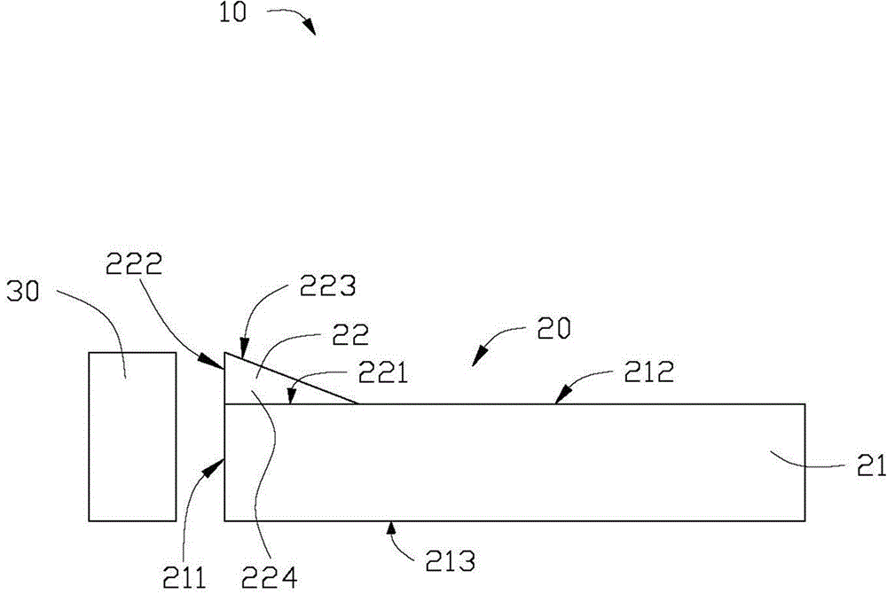
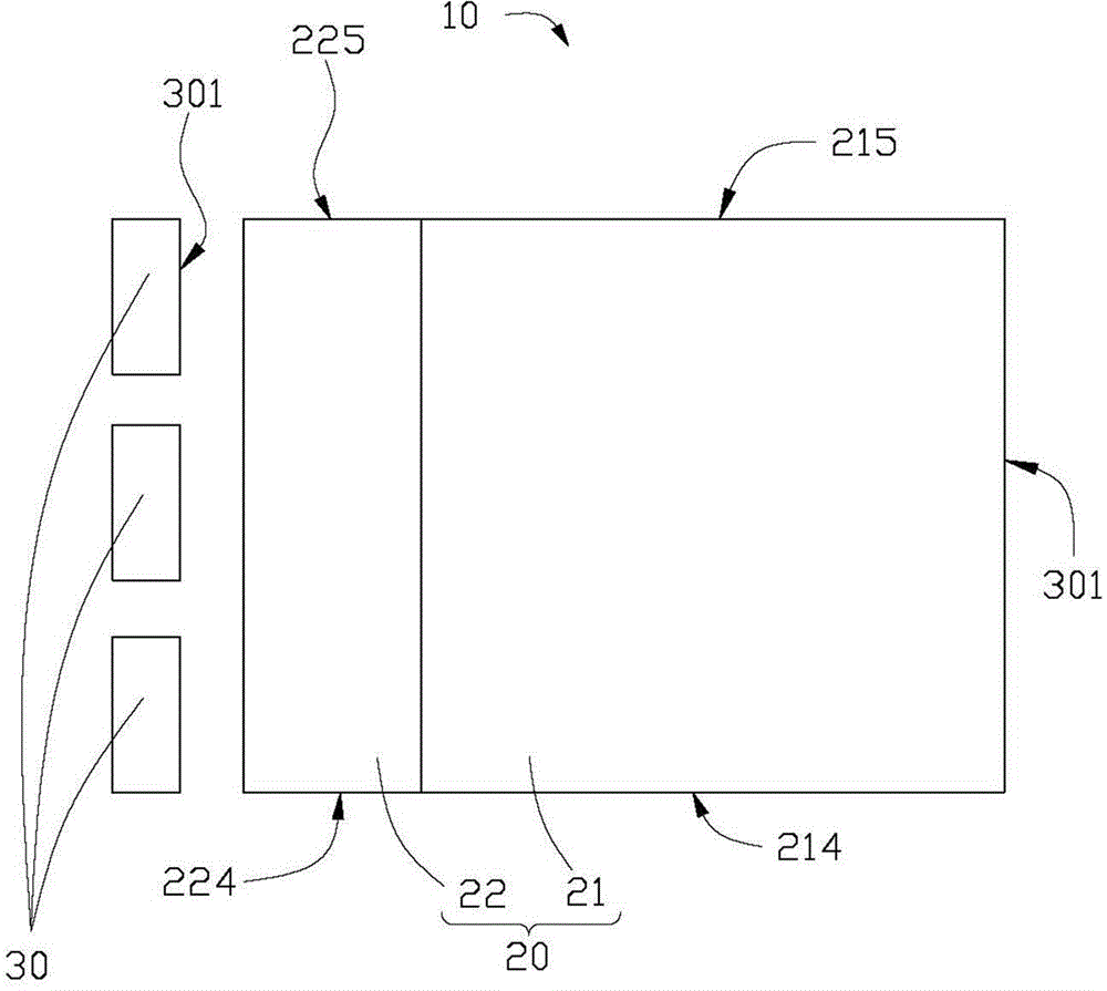
[0018] see figure 1 and figure 2 , the first embodiment of the technical solution provides a backlight module 10 . The backlight module 10 includes a light guide plate 20 and at least one light source 30 .

[0019] The light guide plate 20 includes a light guide body 21 and a light collection structure 22 formed on the light guide body 21 .

[0020] The light guide body 21 can be in the shape of a flat plate or other shapes. In this embodiment, it is in the shape of a flat plate. 212 , the two sides 214 , 215 of the bottom surface 213 . The light emitting surface 212 and the bottom surface 213 are respectively located on opposite sides of the light guide body 21 . The light incident surface 211 is connected between the light exit surface 212 and the bottom surface 213 . The light guide body 21 is made of transparent glass. The reasons for using glass materials are that glass materials have strong thinning ability, high mechanical strength, low absorption rate, wide ligh...


PUM

PropertyMeasurementUnit
refractive indexaaaaaaaaaa

Abstract

A light guide plate comprises a light guide plate body which has an out-light side and an in-light side. The light guide plate further comprises a light gathering structure which is formed on the end surface of the out-light side of the light guide plate body near the in-light side or formed on the in-light side. The light guide plate body is made of glass with a first refractive index, and the light gathering structure is made of a resin material with a second refractive index. The invention further relates to a backlight module containing the light guide plate.

Description

technical field [0001] The invention relates to a light guide plate and a backlight module using the light guide plate. Background technique [0002] Liquid crystal display devices are mainly used in various information, communication, and consumer products, such as personal computers, LCD TVs, mobile phones, video phones, and PDAs. Because the liquid crystal display panel itself cannot emit light, it needs a backlight module to provide it with uniform plane light, so as to obtain good visual effects. [0003] Generally, the light guide plate used in the backlight module is mostly made of resin material, which is manufactured by injection molding. With the thinning of products, the thickness of the required light guide plate is getting thinner and thinner. A thickness of about 0.4mm is the limit of injection molding. Therefore, in electronic products that require a light guide plate with a thickness less than 0.4 mm, glass substrates are generally used to manufacture the l...

Claims


Application Information

Patent Timeline
Patent Type & Authority Applications(China)
IPC IPC(8): G02B6/00G02F1/13357F21V8/00
Inventor 胡朝景戴丰源陈柏洲张欣华
Owner HONG FU JIN PRECISION IND (SHENZHEN) CO LTD
Why Eureka
Try Eureka