Relay control circuit

A relay control and circuit technology, applied in the direction of relays, circuits, electrical components, etc., can solve the problems of increasing volume and cost, and achieve the effect of cost saving, stable and reliable work

Inactive Publication Date: 2016-11-23
SUZHOU ZHIKA INTELLIGENT TECH
View PDF0 Cites 4 Cited by
  • Summary
  • Abstract
  • Description
  • Claims
  • Application Information

AI Technical Summary

Problems solved by technology

[0002] The relay usually requires the control voltage applied to its coil to be higher than its pull-in voltage to work stably and reliably. Therefore, in the relay control circuit powered by low power supply voltage, the use of high pull-in voltage relays is limited. Therefore, it has to In addition, a separate high-voltage power supply is added to the relay control circuit to meet the requirements of the pull-in voltage of the relay, which will increase the volume and cost

Method used


Image

  • Relay control circuit

Examples


Embodiment Construction

[0009] The following will clearly and completely describe the technical solutions in the embodiments of the present invention with reference to the accompanying drawings in the embodiments of the present invention. Obviously, the described embodiments are only some, not all, embodiments of the present invention. Based on the embodiments of the present invention, all other embodiments obtained by persons of ordinary skill in the art without making creative efforts belong to the protection scope of the present invention.

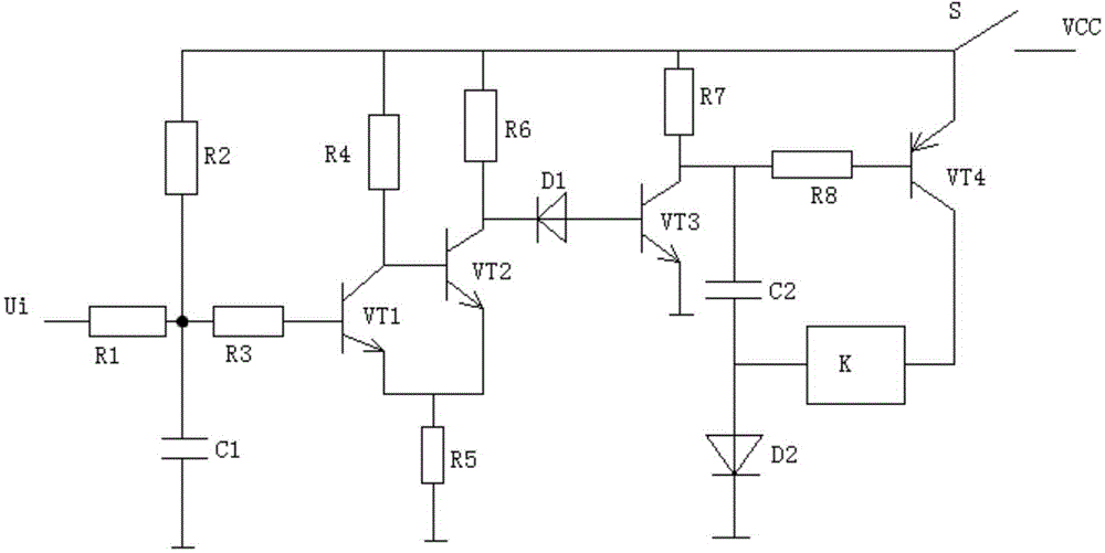
[0010] see figure 1 , in an embodiment of the present invention, a relay control circuit includes a resistor R1, a resistor R2, a capacitor C1, a transistor VT1, a diode D1 and a relay K, one end of the resistor R1 is connected to the input signal Ui, and the other end of the resistor R1 is respectively connected to the resistor R2, the resistor R3 and the grounding capacitor C1, the other end of the resistor R2 is respectively connected to the resistor R4, th...


PUM


Abstract

The invention discloses a relay control circuit. The relay control circuit comprises a resistor R1, a resistor R2, a capacitor C1, a triode VT1, a diode D1 and a relay K. According to the relay control circuit of the invention, based on a principle that the maintaining voltage of a relay is lower than half of the pull-in voltage of the relay, a sufficiently high instantaneous voltage is applied to two ends of the control coil of the relay when the relay is triggered, so that the relay can work stably and reliably in a low-power source voltage supply condition, and therefore, cost can be saved. The relay control circuit is suitable for being popularized.

Description

technical field [0001] The invention relates to a control circuit, in particular to a relay control circuit. Background technique [0002] The relay usually requires the control voltage applied to its coil to be higher than its pull-in voltage to work stably and reliably. Therefore, in the relay control circuit powered by low power supply voltage, the use of high pull-in voltage relays is limited. Therefore, it has to be In addition, a separate high-voltage power supply is added to the relay control circuit to meet the requirements of the pull-in voltage of the relay, which will increase the size and cost. Contents of the invention [0003] The object of the present invention is to provide a relay control circuit under low voltage to solve the problems raised in the background art above. [0004] To achieve the above object, the present invention provides the following technical solutions: [0005] A relay control circuit, comprising a resistor R1, a resistor R2, a capac...

Claims


Application Information

Patent Timeline
Patent Type & Authority Applications(China)
IPC IPC(8): H01H47/00
Inventor 吴臻
Owner SUZHOU ZHIKA INTELLIGENT TECH
Why Eureka
Try Eureka