Moving coil type loudspeaker

一种动圈式扬声器、一起的技术,应用在扩音器、传感器、换能器膜片等方向,能够解决影响扬声器、制约扬声器低频性能、扬声器位移监控准确度有限等问题,达到精确检测的效果

Active Publication Date: 2016-11-23
GOERTEK INC
View PDF9 Cites 15 Cited by
  • Summary
  • Abstract
  • Description
  • Claims
  • Application Information

AI Technical Summary

Problems solved by technology

[0005] However, there is still a certain difference between the theoretical loudspeaker model and the actual product, resulting in limited accuracy of speaker displacement monitoring, which restricts the low-frequency performance of the speaker and affects the performance optimization of the speaker working at low frequencies under high power

Method used


Image

  • Moving coil type loudspeaker
  • Moving coil type loudspeaker
  • Moving coil type loudspeaker

Examples


Embodiment 1

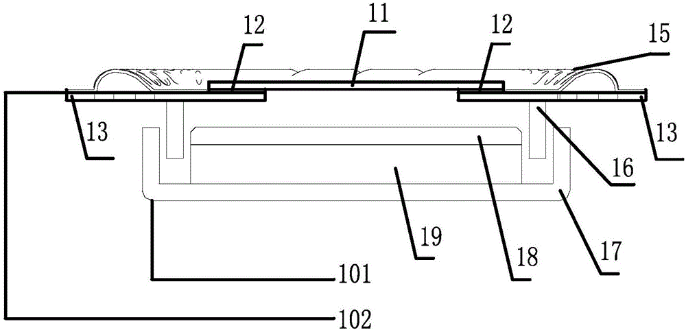
[0040] see figure 1 The structure of the dynamic speaker provided by the first embodiment of the present invention is shown as follows:

[0041] The moving coil loudspeaker includes a vibration system, a magnetic circuit system located below the vibration system, and a housing for accommodating the vibration system and the magnetic circuit system.

[0042] The vibration system includes a diaphragm, a damper 13 , and a voice coil 16 combined from top to bottom. The diaphragm includes a diaphragm body part 15 with a ring and a diaphragm reinforcing part 11 combined at the center below the diaphragm body part 15 . The center of the damper 13 is a hollow structure, and the edge of the damper 13 is fixed to the housing. Wherein, the diaphragm reinforcement part 11 includes a first conductive material layer, the damper 13 includes a second conductive material layer, and the diaphragm reinforcement part 11 and the spider 13 are bonded by a conductive adhesive 12, And the conductiv...

Embodiment 2

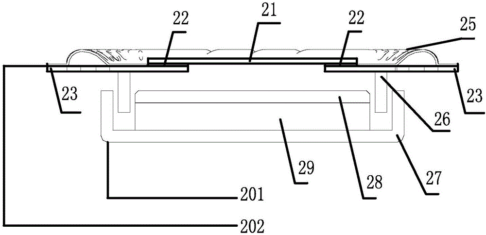
[0052] see figure 2 The structure of the dynamic speaker provided by the second embodiment of the present invention is illustrated as follows:

[0053] The moving coil loudspeaker includes a vibration system, a magnetic circuit system located below the vibration system, and a housing for accommodating the vibration system and the magnetic circuit system.

[0054] The vibration system includes a diaphragm, a damper 23 , and a voice coil 26 combined from top to bottom. The diaphragm includes a diaphragm body part 25 with a ring and a diaphragm reinforcing part 21 combined at a central position below the diaphragm body part 25 . The center of the damper 23 is a hollow structure, and the edge of the damper 23 is fixed with the housing. Wherein, the diaphragm reinforcing part 21 includes a first conductive material layer, and the damper 23 includes a second conductive material layer, and the diaphragm reinforcing part 21 and the spider 23 are bonded by an insulating adhesive 22 ...

Embodiment 3

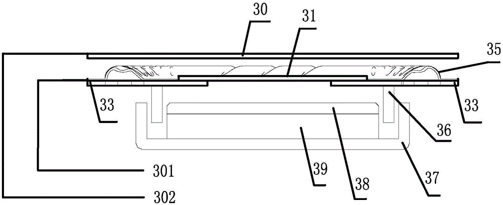
[0063] see image 3 The structure of the dynamic speaker provided by the third embodiment of the present invention is illustrated as follows:

[0064] The moving coil speaker includes a front cover, a vibration system, and a magnetic circuit system from top to bottom, and the moving coil speaker also includes a housing combined with the front cover.

[0065] The vibration system includes a diaphragm, a damper 33 , and a voice coil 36 combined from top to bottom. The diaphragm includes a diaphragm body part 35 with a ring and a diaphragm reinforcing part 31 combined at a central position below the diaphragm body part 35 . The center of the damper 33 is a hollow structure, and the edge of the damper 33 is fixed with the housing. Wherein, the diaphragm reinforcing part 31 includes a first conductive material layer, the damper 33 includes a second conductive material layer, and the diaphragm reinforcing part 31 and the damper 33 are bonded together. Preferably, the whole diaphr...


PUM


Abstract

The invention discloses a moving coil type loudspeaker, which comprises a vibrating system and a magnetic circuit system positioned below the vibrating system, wherein the vibrating system comprises a vibrating film, a centering support chip and a sound coil which are combined together from top to bottom, the vibrating film comprises a vibrating film body part with a folded ring, and a vibrating film reinforcement part combined at the center position below the vibrating film body part; the vibrating film reinforcement part consists of a first conductive material layer, the centering support chip consists of a second conductive material layer, and the vibrating film reinforcement part and the centering support chip are adhered by a conductive binder and are conducted; the magnetic circuit system comprises a central washer, a central magnet and a magnetic conductive yoke which are combined together from top to bottom; the first conductive material layer and the second conductive material layer are used as movable polar plate, and the central washer, the central magnet and the magnetic conductive yoke are used as fixed polar plate, to form a capacitance structure for detecting the vibration displacement of the moving coil type loudspeaker. The vibrating displacement of the moving coil type loudspeaker can be detected by utilizing the capacitance structure provided by the invention.

Description

technical field [0001] The present invention relates to an electroacoustic conversion device, and more specifically, to a dynamic-coil loudspeaker. Background technique [0002] In the prior art, when the loudspeaker is working under low frequency conditions, the problems that limit the maximum power application of the product mainly lie in: [0003] Under high power, the voice coil working under low frequency conditions will produce excessive displacement, and excessive displacement will lead to a sharp increase in distortion, and even obvious rubbing between the voice coil and the magnetic circuit system, which will cause serious damage to the speaker. irreversible damage. [0004] For this problem, the current solution is to use an intelligent power amplifier control unit to control the power fed to the speaker product, and reduce the power when the vibration displacement of the speaker exceeds a predetermined level. This needs to know the vibration displacement of the ...

Claims


Application Information

Patent Timeline
Patent Type & Authority Applications(China)
IPC IPC(8): H04R9/06H04R9/02
CPCH04R9/02H04R9/06H04R2400/11H04R3/007H04R3/002H04R9/025H04R7/125H04R29/003H04R2307/025H04R2499/11H04R2499/15H04R1/06H04R7/04H04R7/06H04R7/10H04R7/18H04R7/24H04R7/20H04R2307/027H04R9/04
Inventor 曹惠娴姜舒杨鑫峰
Owner GOERTEK INC
Why Eureka
Try Eureka