Motor-driven valve

A technology of electric valves and valve seats, applied to valve devices, valve details, engine components, etc., can solve problems such as abnormal sounds and achieve the effect of reducing abnormal sounds

Active Publication Date: 2016-11-30
FUJIKOKI MFG CO LTD
View PDF12 Cites 0 Cited by
  • Summary
  • Abstract
  • Description
  • Claims
  • Application Information

AI Technical Summary

Problems solved by technology

[0004] However, in this type of electric valve, the fluid (refrigerant) flows in both directions, the first flow direction from the first inlet to the second inlet and the second flow direction from the second inlet to the first inlet. When the refrigerant made of gas (gas refrigerant) flows in the first flow direction in the state of excessive gas, when the valve chamber is viewed from the first inlet and outlet side, there is a gap between the left and right parts of the valve port and the inner wall surface of the valve body. Periodic eddy currents occur near the area, and there is a problem of abnormal sound with it

Method used


Image

  • Motor-driven valve
  • Motor-driven valve
  • Motor-driven valve

Examples


Embodiment Construction

[0031] Hereinafter, specific embodiments of the electric valve according to the present invention will be described with reference to the drawings.

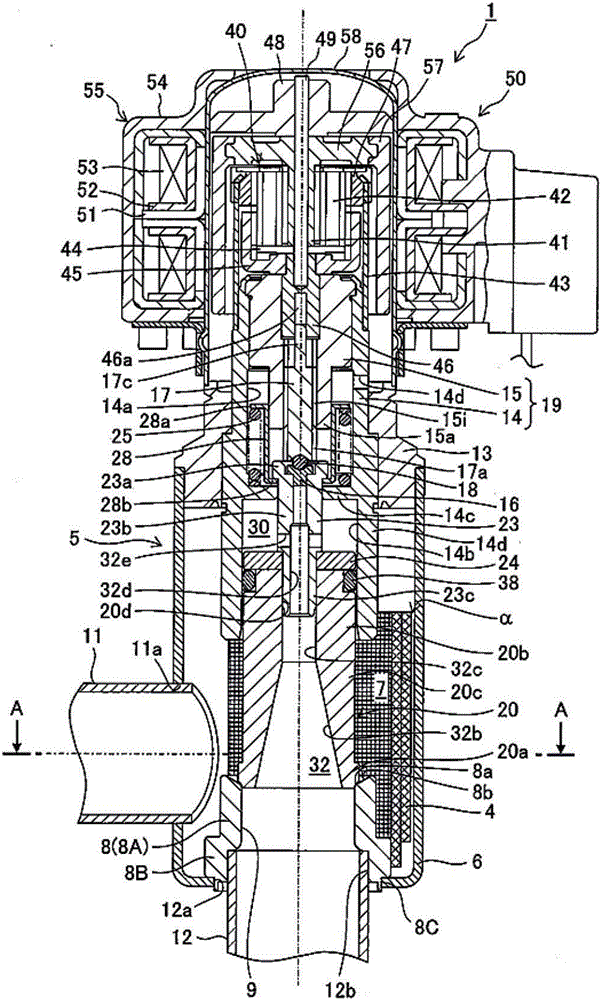
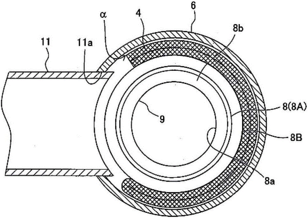
[0032] figure 1 A longitudinal sectional view showing an embodiment of an electric valve according to the present invention, figure 2 express figure 1 The cross-sectional view along the A-A arrow in the middle. In addition, in figure 2 Omit the valve body.

[0033] The electric valve 1 of the illustrated embodiment is used, for example, as an expansion valve in a heat pump type heating and cooling system, and fluid (refrigerant) flows in two directions (a first flow direction and a second flow direction opposite to it), and A bi-directional flow-through electric valve corresponding to a large flow flow path in at least one direction.

[0034]The electric valve 1 mainly includes: a valve body 5 having a cylindrical base body 6 made of a metal plate; a pot 58 fixed on the valve body 5; The supporting member 19; the valve ...


PUM


Abstract

Provided is a motor-driven valve with a simple configuration that is capable of suppressing flow rate loss of fluid and reducing noise caused by the flow of the fluid in the first flowing direction and the second flowing direction, without greatly changing a conventional motor-driving valve. A porous body (4) is fixed to a valve seat member (8), the porous body (4) being extended at least to be lateral to a valve port (9) and having a cutout part corresponding to a first opening (11a) provided at a lateral part of a valve body (5).

Description

technical field [0001] The invention relates to an electric valve, for example, an electric valve used in a heat pump heating and cooling system. Background technique [0002] For a long time, research and development of electric valves aimed at miniaturization, large capacity, and power saving have been ongoing. As an example of such a conventional electric valve, Patent Document 1 discloses a technique that reduces the force acting in the valve closing direction as much as possible and enables the use of a valve opening spring with a smaller spring load. [0003] The electric valve disclosed in Patent Document 1 includes: a valve main body having a valve chamber, a lateral first port opening to the valve chamber, a longitudinal valve port with a valve seat opening to the valve chamber, and The second inlet and outlet connected to the valve port; the valve body, which is arranged in the valve chamber in a form that can be raised and lowered to open or close the valve port;...

Claims


Application Information

Patent Timeline
Patent Type & Authority Applications(China)
IPC IPC(8): F16K31/04F16K47/02
CPCF16K31/04F16K47/02F25B41/35F25B41/38F25B2500/12Y02B30/70F16K31/047F16K47/14
Inventor 原田贵雄田渕健资浅野哲平
Owner FUJIKOKI MFG CO LTD
Why Eureka
Try Eureka