Battery pack for vehicle

A technology for battery packs and vehicles, which is applied in the direction of batteries, battery pack components, and vehicle energy storage. It can solve the problems of large cooling fan pressure loss and complex cooling air flow, so as to improve design freedom and reduce design restrictions. Effect

Active Publication Date: 2016-11-30
ENVISION AESC JAPAN LTD
View PDF6 Cites 6 Cited by
  • Summary
  • Abstract
  • Description
  • Claims
  • Application Information

AI Technical Summary

Problems solved by technology

Therefore, the size of the battery pack in the vehicle width direction becomes easy to further expand

Method used


Image

  • Battery pack for vehicle
  • Battery pack for vehicle
  • Battery pack for vehicle

Examples


Embodiment Construction

[0018] In the following detailed description, for purposes of explanation, numerous specific details are set forth in order to provide a thorough understanding of the disclosed embodiments. It may be evident, however, that one or more embodiments may be practiced without these specific details. In other instances, well-known structures and devices are shown schematically in order to simplify the drawings.

[0019] Hereinafter, an embodiment of the present invention will be specifically described with reference to the drawings.

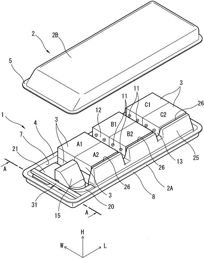
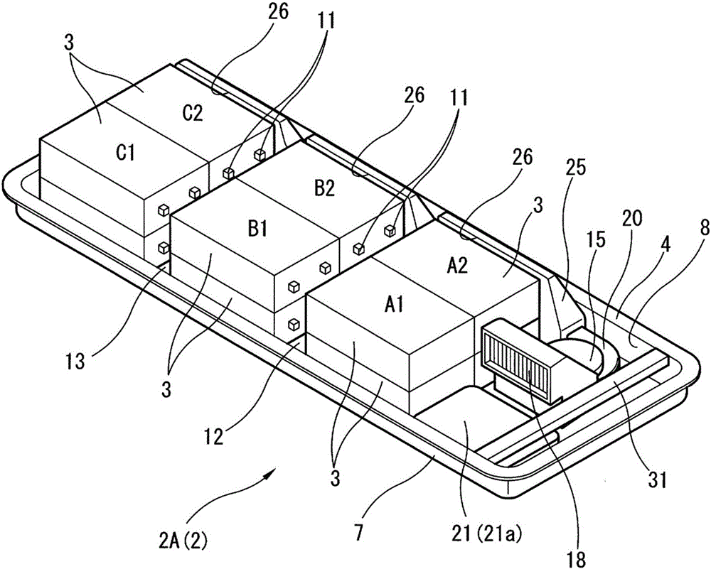
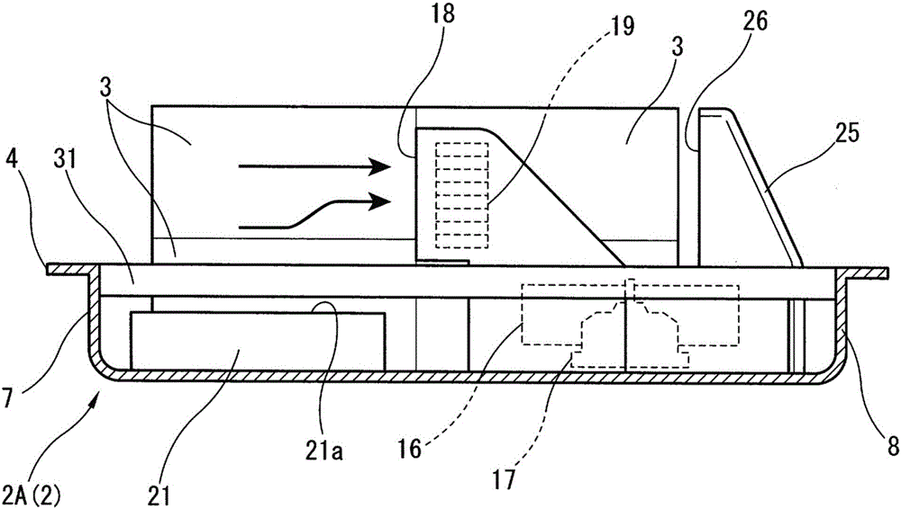
[0020] Figure 1 ~ Figure 4 One example of the battery pack 1 according to the embodiment of the present invention is shown. The battery pack 1 is applied to smaller electric vehicles. The battery pack 1 is configured to house a plurality of battery modules 3 in a substantially rectangular battery case 2 .

[0021] Such as figure 1 As shown, the battery case 2 can be divided into two parts of a battery case lower member 2A as a member forming the ...


PUM


Abstract

Provided is a battery pack for a vehicle including an approximately rectangular pack case, a plurality of flat box-shaped battery modules, a cooling unit, and a junction box for storing a relay, in which: the plurality of battery modules is piled up flat in the pack case so that a terminal provided on a short side of each battery module is directed in a longitudinal direction of the pack case; the cooling unit is disposed at one end of the pack case in the longitudinal direction and configured to send and circulate cooling air in the pack case along an outer periphery of the pack case; and the junction box is disposed in a most downstream side of the circulating cooling air beside the cooling unit in a width direction of the pack case.

Description

[0001] Cross References to Related Applications [0002] This application claims the priority of Japanese Patent Application No. 2015-103337 submitted to the Japan Patent Office on May 21, 2015, and therefore the entire content of said Japanese Patent Application is incorporated herein by reference. technical field [0003] The present invention relates to a battery pack for vehicles. Background technique [0004] A large-capacity secondary battery is required to drive the vehicle. Therefore, as a vehicle battery pack, as shown in Japanese Patent Laid-Open Publication No. 2013-171662 and Japanese Patent Laid-Open Publication No. 2015-26428, it is known that a plurality of flat box-shaped battery modules are housed. A battery pack formed inside a battery case. [0005] Here, in Japanese Patent Laid-Open Publication No. 2013-171662, a part of the battery modules are laid flat (a form in which the main surface of the battery module is substantially parallel to the bottom surf...

Claims


Application Information

Patent Timeline
IPC IPC(8): H01M10/625H01M10/613H01M10/6561H01M2/10H01M50/204H01M50/224H01M50/238H01M50/249H01M50/296
CPCH01M10/613H01M10/625H01M10/6561H01M2220/20H01M50/238H01M50/296H01M50/224B60L50/64H01M50/204H01M50/249H01M10/663H01M10/647H01M10/667H01M10/6565B60L2240/545B60L58/26Y02E60/10Y02T10/70B60K11/06B60K1/04B60K2001/005Y02P70/50H01M10/6566H01M10/0413H01M10/0525H02G3/08
Inventor 林弘一杨琪晔高松俊文
Owner ENVISION AESC JAPAN LTD
Why Eureka
Try Eureka