Bone plate
A bone plate and bone technology, applied in the medical field, can solve the problem of inconvenient removal of a memory alloy bone plate, and achieve the effects of simple structure, convenient disassembly, and short time consumption
- Summary
- Abstract
- Description
- Claims
- Application Information
AI Technical Summary
Problems solved by technology
Method used
Image

Examples
no. 1 example
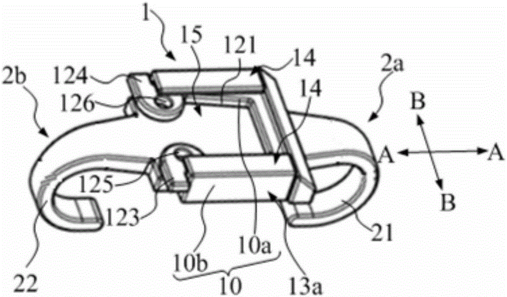
[0048] refer to Figure 1 ~ Figure 3 , the present embodiment provides a bone plate, the bone plate includes a bone positioning part 1, which matches the shape of the part to be boned; The two sides are used to surround and fix the bone-synthesis site;
[0049] All the embracing arms are divided into two groups, the first embracing arm group 2a located on one side of the bone positioning part 1 and the second embracing arm group 2b located on the other side of the bone positioning part 1;
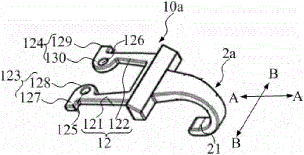
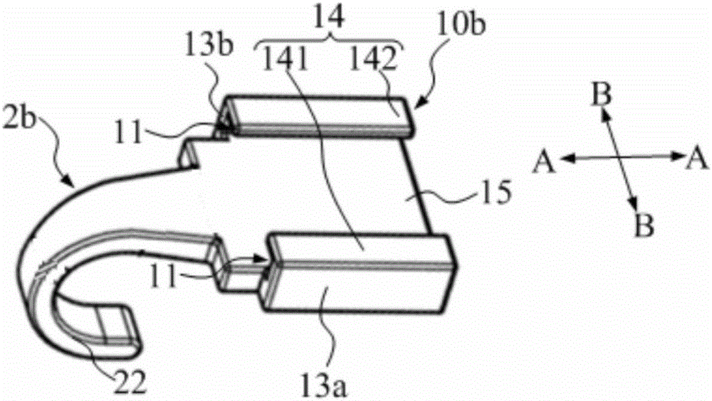
[0050] The bone positioning part 1 is divided into at least two sub-positioning parts 10, among the two sub-positioning parts 10 connected to each other, one of the sub-positioning parts 10 has an accommodation space 11, and the other sub-positioning part 10 has an insert 12, and the insert 12 is inserted into the accommodation space After 11, the two sub-positioning parts 10 are fixedly connected, and the insert 12 can be pulled out from the accommodating space 11.
[0051] Compared with...
no. 2 example
[0076] Compared with the first embodiment, the differences of this embodiment are:
[0077] refer to Figure 4 , the first embracing arm set 2a' includes two first embracing arms 21', and the second embracing arm set 2b' includes two second embracing arms 22'. This can meet the need for embracing when the length of the bone-synthesized part is long, and multiple embracing arms are integrally fixed on the corresponding sub-positioning parts, the structure is compact, and the installation and disassembly save time and effort.
[0078] refer to Figure 4, the first sub-positioning part 10a' has a fixed end C, the inserts 12' are fixed on the fixed end C, and the two first embracing arms 21' in the first embracing arm group 2a' are fixed on the fixed end C. The first embracing arm 21 ′ includes an extension portion 210 and an embracing portion 211 , the extension portion 210 is fixed on the first sub-positioning portion 10 a, and the embracing portion 211 is used for embracing a...
no. 3 example
[0085] refer to Figure 6 ~ Figure 8 , different from the first embodiment, the plug-in method of the two sub-positioning parts in this embodiment is as follows: the inserter is inserted into the accommodating space along the second direction BB.
[0086] Specifically, in the two sub-positioning parts connected to each other, wherein the sub-positioning part includes a mounting arm extending toward the other sub-positioning part along the first direction, the two mounting arms of the two sub-positioning parts are along the The second direction is opposite to each other, and the first direction is the direction in which the first and second sets of embracing arms are opposite to each other. For example, the first sub-positioning part 10c includes a first mounting arm 101 extending toward the second sub-positioning part 10d along the first direction AA, and the second sub-positioning part 10d includes a first mounting arm 101 extending toward the first sub-positioning part 10c a...
PUM
 Abstract
Description
Claims
Application Information
 - R&D
- Intellectual Property
- Life Sciences
- Materials
- Tech Scout
- Unparalleled Data Quality
- Higher Quality Content
- 60% Fewer Hallucinations
Browse by: Latest US Patents, China's latest patents, Technical Efficacy Thesaurus, Application Domain, Technology Topic, Popular Technical Reports.
© 2025 PatSnap. All rights reserved.Legal|Privacy policy|Modern Slavery Act Transparency Statement|Sitemap|About US| Contact US: help@patsnap.com