Electrostatic dust remover and cathode system thereof

An electrostatic precipitator and cathode technology, which is applied in the field of electrostatic precipitator and cathode system, can solve the problems of unadjustable position, inability to increase the operating voltage, and affect the operating efficiency of the electrostatic precipitator, so as to reduce the difficulty of installation and improve the fault tolerance of production and installation rate, to ensure the effect of dust removal efficiency

Inactive Publication Date: 2016-12-07
HANGZHOU TEAMS ENVIRONMENTAL PROTECTION ENG
View PDF7 Cites 3 Cited by
  • Summary
  • Abstract
  • Description
  • Claims
  • Application Information

AI Technical Summary

Problems solved by technology

If the safe discharge distance from the cathode line to the anode plate is d1, and the safe discharge distance from the cathode line to the edge of the anode plate is d2, to ensure the normal corona discharge of the cathode line, d2≧2d1 must be ensured; otherwise, the cathode The wire will first break down and discharge the edge of the anode plate, resulting in the failure of the operating voltage to increase, the normal corona phenomenon cannot be produced, and the design efficiency of the electrostatic precipitator cannot be achieved.
The existing electrostatic precipitator, especially the electrostatic precipitator that adopts the form of one plate with multi-wire pole matching, often needs to readjust the cathode wire after the airlift test, so that the cathode wire can be discharged normally due to the problem of installation accuracy. , and the current pole wire connectors used to fix the cathode wire are usually welded on the cathode frame, and the position cannot be adjusted. You can only break the tip of the cathode wire that is discharged in advance on the cathode wire or directly cut it short to remove individual cathode wires, which directly affects the static electricity. Operating Efficiency of Dust Collector

Method used


Image

  • Electrostatic dust remover and cathode system thereof
  • Electrostatic dust remover and cathode system thereof
  • Electrostatic dust remover and cathode system thereof

Examples


Embodiment Construction

[0018] The core of the present invention is to provide a cathode system of an electrostatic precipitator, the structure design of which can make the position of the cathode line adjustable to ensure higher dust removal efficiency. Another object of the present invention is to provide an electrostatic precipitator comprising the above-mentioned cathode system.

[0019] In order to enable those skilled in the art to better understand the solution of the present invention, the present invention will be further described in detail below in conjunction with the accompanying drawings and specific embodiments.

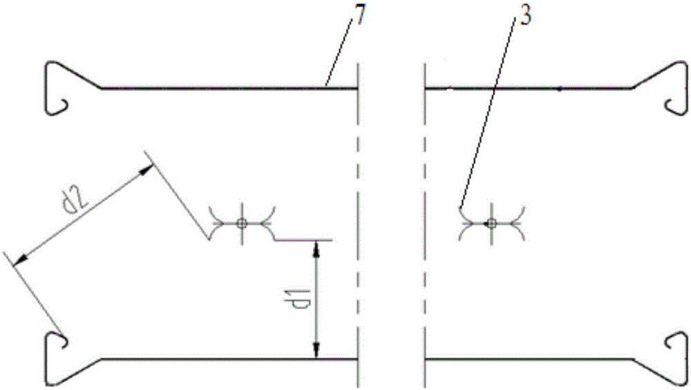
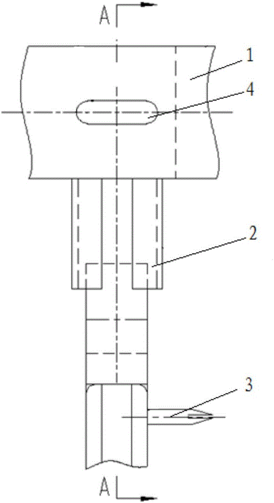
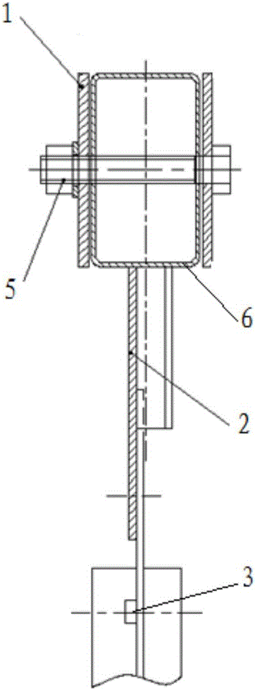
[0020] Please refer to Figure 1 to Figure 3 , figure 1 A structural principle diagram of a specific embodiment of the electrostatic precipitator provided by the present invention; figure 2 A structural schematic diagram of a specific embodiment of the cathode system of the electrostatic precipitator provided by the present invention; image 3 for figure 2 A-A cutaway v...


PUM


Abstract

The invention discloses a cathode system of an electrostatic dust remover. The cathode system comprises a cathode frame, a cathode line connecting piece and a cathode line used for discharge. A through groove is formed in the cathode frame. One end of the cathode line connecting piece is fixedly connected with the cathode line, the other end of the cathode line connecting piece is connected with the through groove, and the cathode line connecting piece can move in the length direction of the through groove. The through groove is formed in the cathode frame, and therefore the cathode line connecting piece can move in the length direction of the through groove, that is, the position of the cathode line can be adjusted; the position of the cathode line can be adjusted, and therefore after the electrostatic dust remover is mounted, the position of the cathode line can be adjusted in real time according to needs so as to guarantee the safety distance between the cathode line and an anode plate; and therefore mounting difficulty can be reduced, the production and mounting error-tolerant rate can be increased, and the dust removal efficiency of the electrostatic dust remover can be guaranteed. The invention further discloses the electrostatic dust remover including the cathode system.

Description

technical field [0001] The invention relates to the field of electrostatic precipitators, in particular to a cathode system of an electrostatic precipitator. In addition, the present invention also relates to an electrostatic precipitator comprising the above-mentioned cathode system. Background technique [0002] Electrostatic precipitator is a kind of gas dedusting method. Its working principle is to use high-voltage electric field to ionize the dust-containing gas. After the dust particles in the gas are combined with negative ions to be negatively charged, they tend to discharge and deposit on the surface of the anode, thereby realizing gas purification. Due to its low energy consumption and high dust removal efficiency, it is widely used in metallurgy, mining, chemical and power generation industries. [0003] The voltage of the electric field between the anode plate and the cathode wire has a great influence on the dust removal efficiency. To ensure that the electric ...

Claims


Application Information

Patent Timeline
Patent Type & Authority Applications(China)
IPC IPC(8): B03C3/43B03C3/04
CPCB03C3/43B03C3/04
Inventor 马建中任燕骆彬翼徐斌杨浩卢星宇
Owner HANGZHOU TEAMS ENVIRONMENTAL PROTECTION ENG
Why Eureka
Try Eureka