Automatic reciprocating spraying device

A spraying device, a reciprocating technology, applied to the spraying device and other directions, can solve the problems such as the inability to guarantee the uniformity and stability of the coating on the surface of the workpiece, the difficulty in installation and debugging, and the complex structure, and achieve economical and movement accuracy. and easy maintenance, flexible and simple structure

Inactive Publication Date: 2016-12-07
QINGDAO UNIV OF SCI & TECH
View PDF10 Cites 8 Cited by
  • Summary
  • Abstract
  • Description
  • Claims
  • Application Information

AI Technical Summary

Problems solved by technology

In the past automatic reciprocating spraying devices, the reciprocating motion of the spraying table mostly uses a linear motion unit combined with a linear guide rail and a ball screw. The structure is relatively complicated, the installation and debugging are relatively difficult, and the cost is high.
However, the use of synchronous belt and chain transmission to drive the working platform has the disadvantages of low positioning accuracy and poor running stability.
In addition, for pipe and rod workpieces that only need to be sprayed on the middle part, manual hand-held spray guns are often used for spraying. Manual spraying is inefficient and cannot guarantee the uniformity and stability of the surface coating of the workpiece.

Method used


Image

  • Automatic reciprocating spraying device
  • Automatic reciprocating spraying device
  • Automatic reciprocating spraying device

Examples


Embodiment Construction

[0027] The specific process of the present invention will now be described through the following embodiments in conjunction with the accompanying drawings.

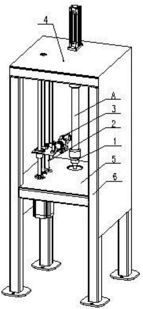
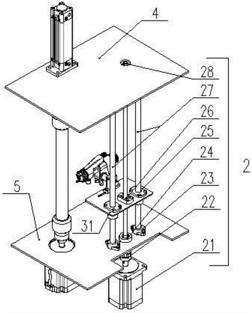
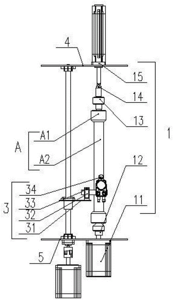
[0028] As shown in the drawings, an automatic reciprocating spraying device of the present invention includes a frame 6, an upper mounting plate 4, a lower mounting plate 5, a spraying workpiece assembly A, a clamping and rotating unit 1, a spraying adjustment unit 3 and a reciprocating unit 2. Frame 6 is welded by twelve square tubes, four base plates and steel plates on both sides; The spraying workpiece assembly A includes a protective cover A1 and a workpiece A2, and the two protective covers A2 are installed at both ends of the workpiece A1 to protect the two ends of the workpiece A1 from being sprayed.

[0029] The clamping and rotating motion unit 1 includes a No. 1 stepper motor 11, a fixed lower center 12, a rotatable upper center 13, a locknut 14 and a clamping cylinder 15; the No. 1 stepper motor 11 is fixed o...


PUM


Abstract

The invention discloses an automatic reciprocating spraying device. The automatic reciprocating spraying device mainly comprises a workpiece spraying assembly, a clamping rotating movement unit, a spraying adjusting unit and a reciprocating movement unit. The workpiece spraying assembly comprises a protection sleeve and a workpiece. The clamping rotating movement unit comprises a first stepping motor, a fixed lower tip, a self-rotation upper tip, a lock nut and a clamping air cylinder. The spraying adjusting unit comprises a spraying platform, a T-shaped guiding shaft support, a connecting shaft and a spray gun. The reciprocating movement unit comprises a second stepping motor, a coupler, a ball screw, a fixing side support, a supporting side support, guiding shafts, linear bearings and a guiding shaft support. Upright fixing of the workpiece is guaranteed through the fixed lower tip and the self-rotation upper tip, pressing and detaching of the workpiece are achieved through the clamping air cylinder, the spraying platform is connected with the linear bearings on the guiding shafts and a nut on the ball screw, and the linear movement of the spraying platform is achieved; and the stepping motor drives the workpiece to do the rotation movement, and the automatic reciprocating spraying device can guarantee the spraying thickness and uniformity for the sprayed workpiece.

Description

technical field [0001] The invention relates to an automatic reciprocating spraying device, in particular to a device for uniformly spraying the outer surface of a long tube rod workpiece along the axis and circumferential direction. Background technique [0002] In industrial production, the surface of most pipe and rod parts needs to be attached with special coatings to achieve specific functions. For this type of workpiece, there are three most commonly used processing methods: spray coating, roller coating and dip coating. The roller coating method and the dip coating method do not strictly control the coating thickness and the coating uniformity is poor, while the spray coating method has great advantages in terms of coating thickness and uniformity. [0003] In the automatic reciprocating spraying device, most of them use the clamping device to clamp the workpiece, and realize the spraying on the surface of the workpiece by means of the rotary motion of the workpiece ...

Claims


Application Information

Patent Timeline
Patent Type & Authority Applications(China)
IPC IPC(8): B05B13/04B05B13/02B05B15/08B05B15/68
CPCB05B13/0228B05B13/041B05B15/68
Inventor 白跃峰杭柏林许恩乐段振亚
Owner QINGDAO UNIV OF SCI & TECH
Why Eureka
Try Eureka