Cutter bar device of multi-functional digital controlled lathe

A CNC lathe, multi-functional technology, applied in the direction of tool holders, etc., can solve the problems of increasing the assembly complexity of the clamping device, no positioning structure, and inaccurate installation of the clamping groove, so as to save tool change and tool setting time, The effect of improving production efficiency, improving processing accuracy and pass rate

Active Publication Date: 2016-12-07
浙江金本汽车零部件有限公司
View PDF11 Cites 10 Cited by
  • Summary
  • Abstract
  • Description
  • Claims
  • Application Information

AI Technical Summary

Problems solved by technology

[0004] However, the tool clamping device provided above uses clamping grooves installed around the tool holder, and the structure of each clamping groove is not the same, which increases the complexity of the assembly of the clamping device, and the distance between the tool holder and the clamping groove There is no positioning structure between them, making the installation of the clamping groove imprecise

Method used


Image

  • Cutter bar device of multi-functional digital controlled lathe
  • Cutter bar device of multi-functional digital controlled lathe
  • Cutter bar device of multi-functional digital controlled lathe

Examples


Embodiment Construction

[0032] The following are specific embodiments of the present invention and in conjunction with the accompanying drawings, the technical solutions of the present invention are further described, but the present invention is not limited to these embodiments.

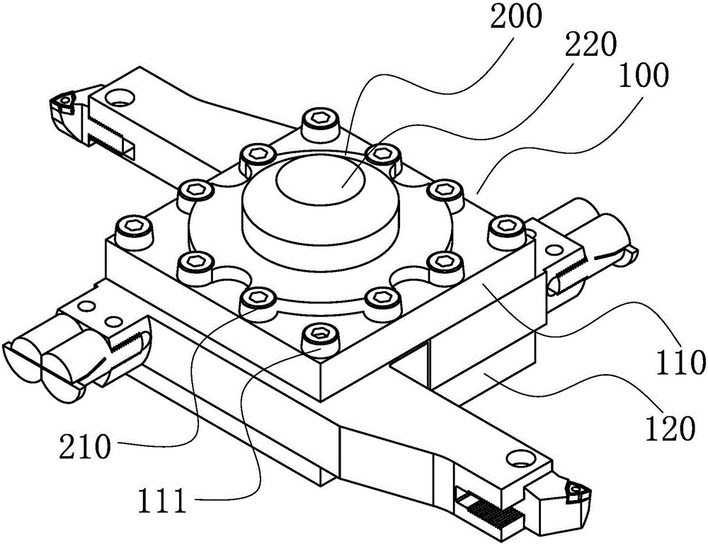
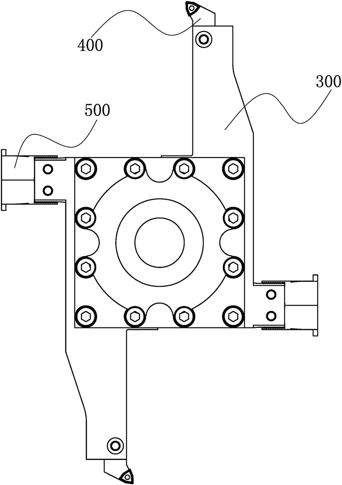
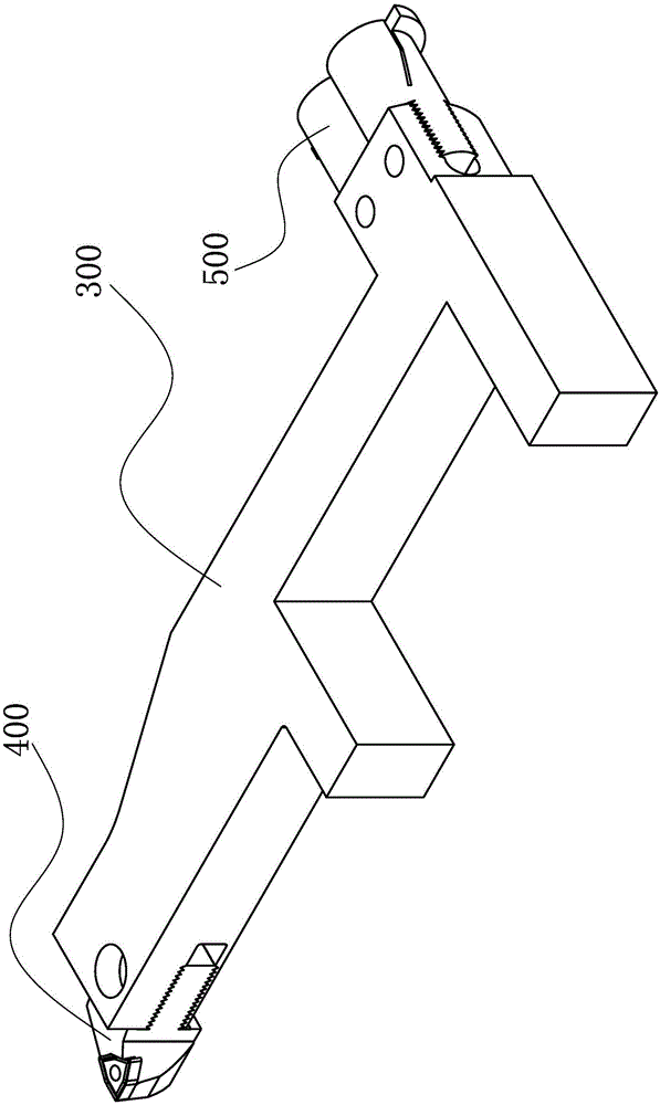
[0033] Such as figure 1 with figure 2 As shown, a kind of multifunctional numerical control lathe tool holder device provided by the present invention comprises: a tool rest 100, a first flat plate 110 and a second flat plate 120 are arranged along the thickness direction of the tool rest 100, and the first flat plate 110 and the second flat plate Two flat plates 120 are integrally formed; a rotating shaft seat 200 is revolving, and a plurality of first through holes 210 are arranged in a circular array along the axial direction of the rotating shaft seat 200, and the rotating shaft seat 200 is fixed on the tool holder 100 by threaded fasteners ; Two knife rods 300 are symmetrically arranged on both sides of the knife ho...


PUM


Abstract

The invention provides a cutter bar device for a multi-functional digital controlled lathe. The cutter bar device comprises a cutter frame, a rotation shaft seat, two cutter bars, two outer-circle cutter bodies and four internal-groove cutter bodies; a first flat plate and a second flat plate are installed in the thickness direction of the cutter frame, and the first flat plate and the second flat plate are integrally molded; the rotation shaft seat is of a rotary shape, a plurality of first through holes are formed in the axial direction of the rotation shaft seat in a circular array mode, and the rotation shaft seat is fixed to the cutter frame through threaded fasteners; the two cutter bars are arranged on the two sides of the cutter frame in central symmetry, clamped between the first flat plate and the second flat plate, and fixed to the cutter frame through threaded fasteners; the two outer-circle cutter bodies are installed at one ends of the two cutter bars correspondingly; and the four internal-groove cutter bodies are installed at the other ends of the two cutter bars correspondingly. According to the cutter bar device, the cutter bars and the cutter frame are positioned through U-shaped grooves and fixed through the threaded fasteners, so that the installation of the cutter bars and the cutter frame is stable, relative sliding and relative rotation between the cutter bars and the cutter frame are prevented, and machining precision and percent of pass of workpieces are improved.

Description

technical field [0001] The invention belongs to the technical field of machining, and relates to a cutter rod device, in particular to a multifunctional numerical control lathe cutter rod device. Background technique [0002] At present, the tool holders of most CNC lathes are divided into purchased standard tool holders and self-made cutter holders; The tool holder of the lathe can hold up to 4 tools, and can only process 4 types of workpieces at most. Some complex products require more than 4 types of tools for processing, and the tool holder needs to be manually replaced up and down to complete the processing. In this way, the efficiency of manual work is low and the cost of the enterprise is increased; the surface of the traditional round tool holder is smooth, and the tool holder and the machine tool clamping head are easy to slip during the processing, which affects the quality of the processed parts. precision. [0003] Chinese invention patent (CN 104551056 A) disc...

Claims


Application Information

Patent Timeline
Patent Type & Authority Applications(China)
IPC IPC(8): B23B29/24B23B29/26
CPCB23B29/244B23B29/26
Inventor 肖鹿
Owner 浙江金本汽车零部件有限公司
Why Eureka
Try Eureka