Rotary swing type welding torch and welding method

A welding torch and contact tip technology, applied in the field of welding and narrow gap welding, can solve problems such as poor fusion of groove side walls, and achieve the effects of solving poor fusion, enhancing reliability and high efficiency

Inactive Publication Date: 2016-12-07
HARBIN INST OF TECH AT WEIHAI
View PDF7 Cites 14 Cited by
  • Summary
  • Abstract
  • Description
  • Claims
  • Application Information

AI Technical Summary

Problems solved by technology

[0004] In view of the above current situation of the prior art, the main purpose of the present invention is to provide a welding torch, which can meet the narrow gap welding requirements of large thickness plates, and can solve the problem of poor fusion of the side wall of the groove

Method used


Image

  • Rotary swing type welding torch and welding method
  • Rotary swing type welding torch and welding method

Examples


Embodiment Construction

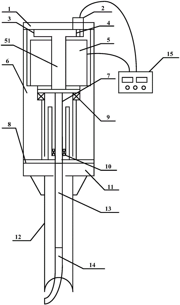
[0026] Aiming at the problems existing in the welding process of large-thickness plates, the first aspect of the present invention provides a rotary-type welding torch, which can successfully perform narrow-gap welding of large-thickness plates.

[0027] Such as figure 1 As shown, a rotary torch of the present invention includes a contact tip 14 , a rotary drive mechanism, and a control device 15 . Wherein, the control device 15 is connected with the swing drive mechanism to control the movement of the swing drive mechanism, and the movement output end of the swing drive mechanism is connected with the contact tip 14, so that Under the control of the control device 15 , the position of the contact tip 14 is adjusted and / or the contact tip 14 is made to perform a swing motion according to preset swing parameters, that is, a rotation motion and / or a swing motion. In the present invention, the swing parameters preferably include swing angle, swing frequency and residence time, e...


PUM


Abstract

The invention provides a rotary swing type welding torch. The rotary swing type welding torch comprises a current contact nozzle, a rotary swing driving mechanism and a control device, wherein the control device is connected with the rotary swing driving mechanism so as to control the rotary swing driving mechanism to move, and the movement output end of the rotary swing driving mechanism is connected with the current contact nozzle so as to adjust the position of the current contact nozzle and/or enable the current contact nozzle to make rotary swing movement according to preset swing parameters. According to the rotary swing type welding torch, two operating modes of swing and rotation can be realized, so that heat input to the side wall of a groove can be increased by virtue of electric arc swing, and the problem of poor fusion of the side wall and the bottom of the groove during narrow gap welding of large-thickness plates is solved. The invention further provides a welding method.

Description

technical field [0001] The invention relates to the field of narrow-gap welding, in particular to the field of welding narrow-gap grooves of large-thickness plates, and in particular to a rotary-swing welding torch. The invention also relates to a welding method. Background technique [0002] In the welding of plates with large thickness (for example, thickness exceeding 40mm), if traditional grooves are used, more deposited metal is required. On the one hand, the welding efficiency is relatively low, and on the other hand, the post-weld deformation is also serious. Both of these problems can be mitigated if narrow clearance grooves can be used. However, for the welding of large-thickness plates, in order to achieve narrow-gap welding, it is necessary to solve the problem of poor fusion of side walls in narrow-gap grooves. Unfortunately, the traditional narrow-gap welding torch cannot adapt to the welding of large-thickness plates, and it is easy to cause a series of probl...

Claims


Application Information

Patent Timeline
Patent Type & Authority Applications(China)
IPC IPC(8): B23K9/28B23K9/26
CPCB23K9/26B23K9/28B23K9/285
Inventor 孙清洁刘一搏吕洋李红伟王亚峰侯少军冯吉才
Owner HARBIN INST OF TECH AT WEIHAI
Why Eureka
Try Eureka