A surface grinding device

A driving device and grinding disc technology, which is applied to grinding driving devices, grinding machines, grinding slides, etc., can solve the problems of inability to grind workpieces, limitation of fixing methods, and large safety hazards, so as to achieve smooth and bright grinding surfaces and avoid the danger of falling off. , the effect of small safety hazards

Active Publication Date: 2019-10-11
山东豪迈精密机械有限公司
View PDF6 Cites 1 Cited by
  • Summary
  • Abstract
  • Description
  • Claims
  • Application Information

AI Technical Summary

Problems solved by technology

[0004] 1. When the angle grinder works, it is in point contact with the workpiece, and the grinding efficiency of the large-area workpiece surface is low
[0005] 2. The grinding disc is in the shape of a disc, so it cannot grind the "corner" shaped workpiece
[0006] 3. For workpieces such as deep and narrow grooves, limited by the overall size of the angle grinder, it is impossible to reach in for grinding
[0007] 4. After the grinding disc is used for a period of time, due to wear, the radius becomes smaller, the line speed decreases, the grinding ability decreases, and it is difficult to see the grinding path
Generally, the remaining third of the grinding disc is not used, resulting in a waste of grinding disc material
[0008] 5. The rotation speed of the grinding disc of the angle grinder is very high, and the inertial energy is very large. If the grinding disc breaks, the broken fragments have high energy and splash around, which is a great safety hazard.
[0009] In view of the above problems, a swing mechanism is used to drive the grinding plate to swing at high speed to grind the surface of the workpiece. Although there are swing devices on the market, the above swing devices are limited by the way the tools are fixed, and the force cannot be too large

Method used


Image

  • A surface grinding device
  • A surface grinding device
  • A surface grinding device

Examples


Embodiment Construction

[0045] In order to facilitate the understanding of those skilled in the art, the present invention will be further described below in conjunction with the accompanying drawings.

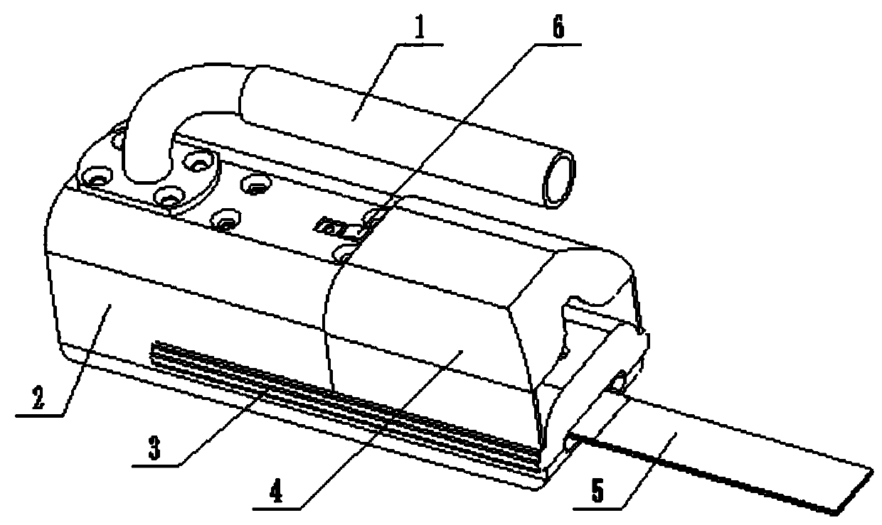
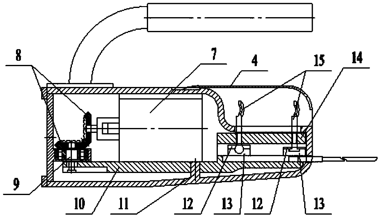
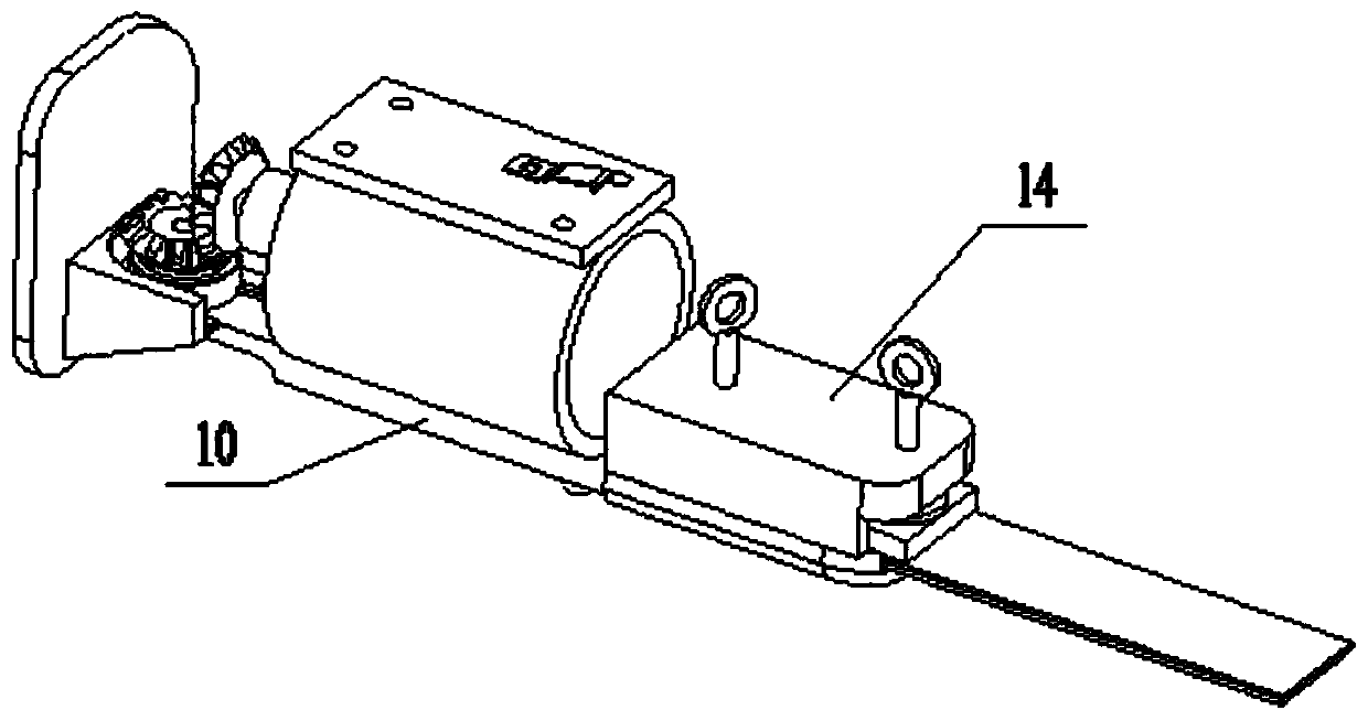
[0046] Such as figure 1 , figure 2 , image 3 As shown, a surface grinding device includes a grinding plate 5 and a swing mechanism, the grinding plate 5 is fixed on the swing mechanism, the swing mechanism is provided with a driving device to drive, and the driving device drives the grinding plate 5 through the swing mechanism Swing, the swing mechanism includes an eccentric shaft 9 and a transmission element 10, one end of the transmission element 10 is provided with an oblong hole 16, the eccentric shaft 9 is perpendicular to the transmission element 10, and the eccentric shaft 9 rotates in the oblong hole 16 to drive The transmission element 10 pivots.

[0047] The other end of the transmission element 10 is provided with a locking bolt connecting seat 14, and the locking bolt connecting seat...


PUM


Abstract

The invention discloses a surface grinding device, and belongs to the field of workpiece grinding. The surface grinding device comprises a grinding sheet and a swing mechanism; the grinding sheet is fixedly arranged on the swing mechanism; the swing mechanism is driven by a drive device; the drive device drives the grinding sheet to swing through the swing mechanism; the swing mechanism comprises an eccentric shaft and a transmission element; a long circular hole is formed in one end of the transmission element; and the eccentric shaft rotates in the long circular hole to drive the transmission element to swing. The surface grinding device solves the grinding problem in a corn-shaped narrow area, further improves grinding efficiency, reduces breakage potential safety hazards of the grinding sheet and reduces cost of the grinding sheet.

Description

technical field [0001] The invention relates to the field of workpiece grinding, in particular to a surface grinding device. Background technique [0002] At present, it is necessary to grind the surface of the workpiece before welding and painting. Angle grinders or grinders are used for occasions where burrs, sharp edges, and surface defects occur at the corners of the workpiece or due to processing. polished. Grinding machines are generally fixed in one place, and the grinding parts need to be picked up for grinding. It is not suitable for grinding large workpieces. For large workpieces and other workpieces that are not suitable for grinding machines, angle grinders are generally used. In the mill, the motor drives the turntable to drive the grinding disc to rotate at high speed. [0003] When using the angle grinder, there are mainly the following problems: [0004] 1. When the angle grinder works, it is in point contact with the workpiece, and the grinding efficiency...

Claims


Application Information

Patent Timeline
Patent Type & Authority Patents(China)
IPC IPC(8): B24B23/00B24B41/02B24B47/00
Inventor 杨广东赵西鹏姜雄德
Owner 山东豪迈精密机械有限公司
Why Eureka
Try Eureka