Fan drainage structure, drainage method of fan drainage structure and manufacturing method of fan drainage structure

A technology for drainage structures and fans, applied in soil drainage, infrastructure engineering, applications, etc., can solve problems such as aggravating the junction between the fan foundation and the foundation ring, increasing the risk of unsafe operation of the fan, and increasing the operation and maintenance cost of the wind farm. To achieve the effect of reasonable drainage, cost control and easy production

Active Publication Date: 2016-12-07
CEEC JIANGSU ELECTRIC POWER DESIGN INST
View PDF6 Cites 4 Cited by
  • Summary
  • Abstract
  • Description
  • Claims
  • Application Information

AI Technical Summary

Problems solved by technology

The junction of the top surface of the fan foundation and the foundation ring is the weak link of the fan foundation. Since the fan is a towering structure, a large amount of rainwater will flow along the tower to this weak part in rainy days. The horizontal bending moment of the fan will cause the top of the fan foundation to Relative displacement occurs at the junction with the foundation ring. At this time, a large amount of rainwater enters the weak part, which intensifies the separation of the junction between the fan foundation and the foundation ring from the outside to the inside, resulting in the corrosion of the steel bars inside the foundation, so that the fan foundation and the foundation ring are no longer one. The overall stress will increase the risk of the wind turbine being seriously tilted or even collapsed due to the pull-out of the foundation ring from the foundation. At the same time, the covering soil on the upper part of the wind turbine foundation plays an important role in the water and soil conservation of the wind farm and the force of the wind turbine foundation. Do waterproof treatment at the junction of the top and the foundation ring, and plant green plants on the upper part of the wind turbine foundation to reduce water and soil erosion. The disadvantage is that a large amount of rainwater will flow down the wall of the wind turbine tower, constantly scouring the plants and covering soil on the top of the foundation, resulting in the weight of the covering soil Reduce and increase the risk of unsafe operation of wind turbines. Waterproof materials are prone to aging and fatigue damage. It is necessary to regularly check and replace the foundation top slope protection, which will increase the operation and maintenance costs of wind farms

Method used


Image

  • Fan drainage structure, drainage method of fan drainage structure and manufacturing method of fan drainage structure
  • Fan drainage structure, drainage method of fan drainage structure and manufacturing method of fan drainage structure

Examples


Embodiment Construction

[0024] The present invention will be further described below in conjunction with the accompanying drawings. The following examples are only used to illustrate the technical solution of the present invention more clearly, but not to limit the protection scope of the present invention.

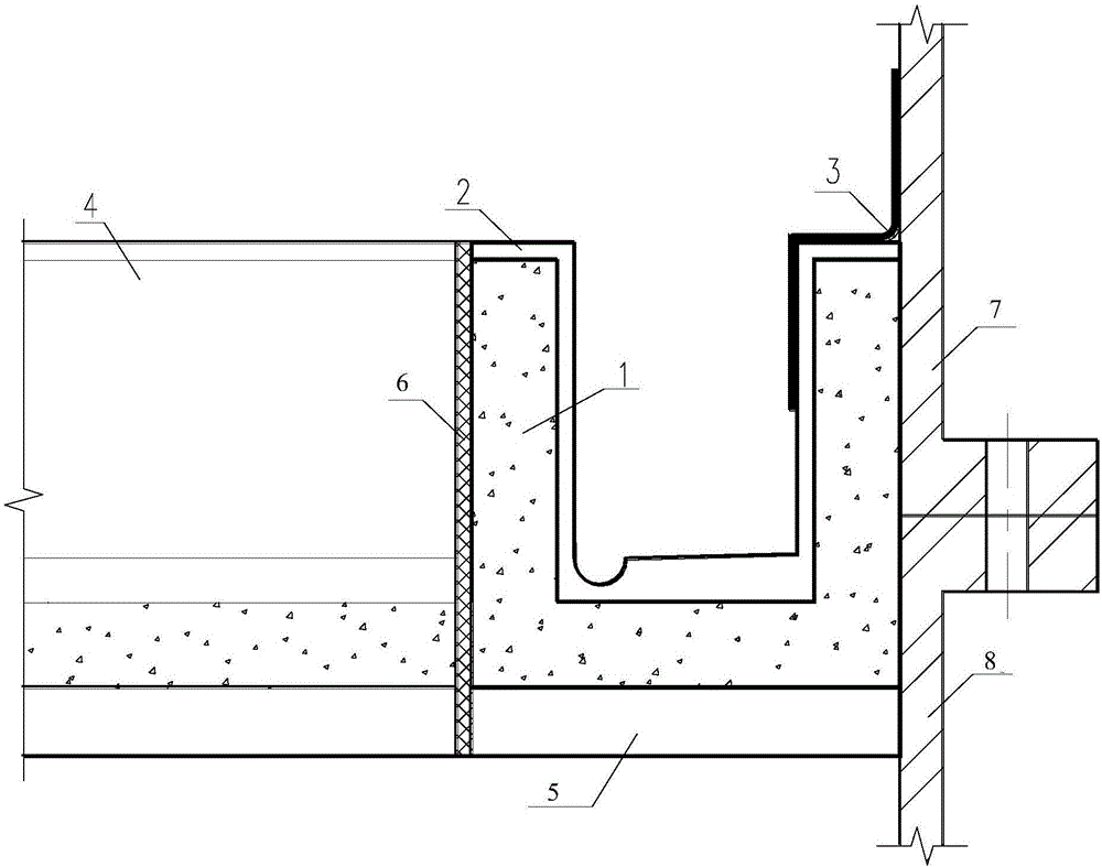
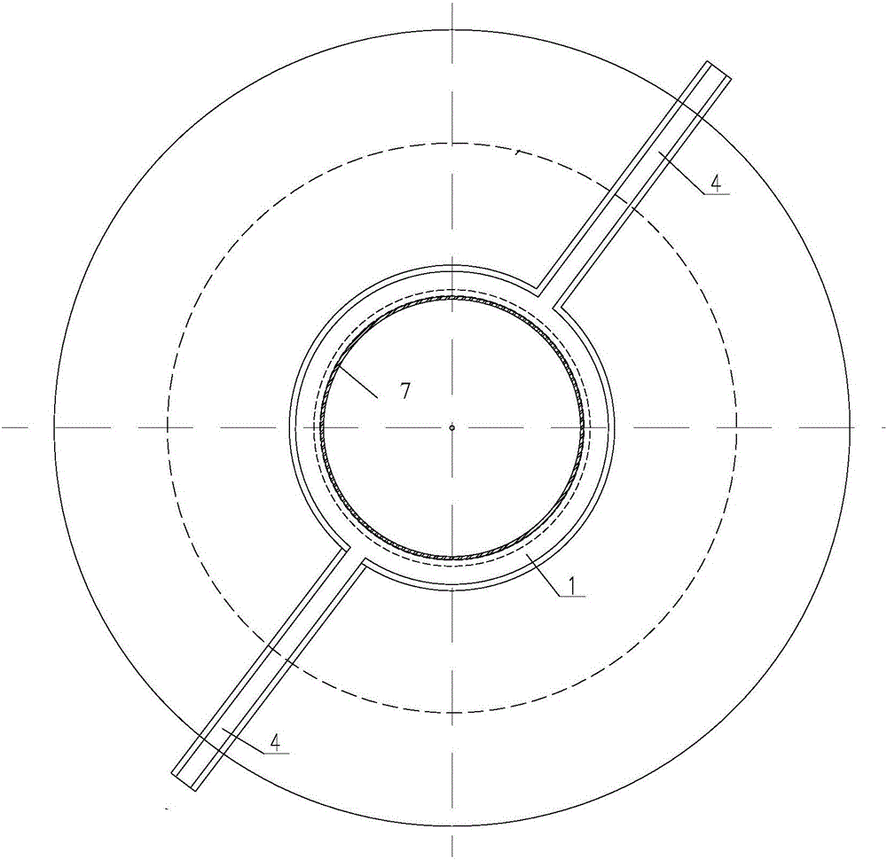
[0025] Such as Figure 1-2 As shown, the present invention provides a fan drainage structure, including an annular drainage ditch arranged along the fan tower and a radial drainage ditch connected with the annular drainage ditch, the annular drainage ditch is located on the top of the fan foundation, and the annular drainage ditch The wall of the ditch is connected with the fan tower through a waterproof membrane, and the inside of the annular drainage ditch and the radial drainage ditch are covered with a layer of waterproof layer.

[0026] The connection between the annular drainage ditch and the radial drainage ditch is provided with a deformation joint, and the deformation joint is caulked ...


PUM


Abstract

The invention provides a fan drainage structure which comprises an annular drainage ditch arranged along a fan tower and radial drainage ditches connected with the annular drainage ditch. The annular drainage ditch is located at the top of a fan foundation, the ditch wall of the annular drainage ditch is connected with the fan tower through a waterproof roll, and the interior of the annular drainage ditch and the interior of each radial drainage ditch are each covered with a waterproof layer. The invention further provides a drainage method of the fan drainage structure. The drainage process is integral, rainwater flowing down along the fan tower can be drained in time through the radial drainage ditches and the annular drainage ditch, the situation that a large amount of rainwater washes soil covering the fan foundation is avoided, and the requirements for the designed covering soil weight and water and soil conservation of the fan foundation are met. In addition, the invention provides a manufacturing method of the fan drainage structure. The manufacturing method is simple and easy to implement.

Description

technical field [0001] The invention relates to a fan drainage structure, a drainage method and a manufacturing method thereof, and belongs to the technical field of water and soil conservation of wind farms and fan foundation protection. Background technique [0002] Wind power generation is an important part of national green energy construction, and onshore wind farms are one of the main forms of wind power generation. The junction of the top surface of the fan foundation and the foundation ring is the weak link of the fan foundation. Since the fan is a towering structure, a large amount of rainwater will flow along the tower to this weak part in rainy days. The horizontal bending moment of the fan will cause the top of the fan foundation to Relative displacement occurs at the junction with the foundation ring. At this time, a large amount of rainwater enters the weak part, which intensifies the separation of the junction between the fan foundation and the foundation ring...

Claims


Application Information

Patent Timeline
Patent Type & Authority Applications(China)
IPC IPC(8): E02D27/42E02B11/00
CPCE02B11/00E02D27/425
Inventor 王广兵张源王磊吉春明李素良黄万山王泽国刘欣良彭秀芳张瑞云陈勖
Owner CEEC JIANGSU ELECTRIC POWER DESIGN INST
Why Eureka
Try Eureka