
Ocean current retaining wall and construction method thereof

A technology of retaining walls and ocean currents, applied in sheet pile walls, infrastructure engineering, protection devices, etc., can solve the problems of high maintenance cost, high cost and poor effect of anti-scour effect.

Pending Publication Date: 2021-02-26
TIANJIN UNIV
View PDF2 Cites 0 Cited by
  • Summary
  • Abstract
  • Description
  • Claims
  • Application Information

AI Technical Summary

Problems solved by technology

Patent 201810328155.6 introduces an anti-scour structure for offshore wind power generation foundations. Sand and gravel are laid within a certain range around the pile foundation to form a sand scour surface, which has a good anti-scour effect in a short period of time, but there are inevitably gaps between the sand and gravel. The effect is not good under the cumulative effect of ocean currents and tides, and the maintenance cost of maintaining the anti-scouring effect is relatively high
Patent 201910795899.3 introduces an anti-scour structure and construction method of steel pipe pile foundations. The anti-scour capability of steel pipe piles can be effectively improved by reinforcing the steel pipe piles, but all foundations need to be reinforced and the cost is high.

Method used


Image

  • Ocean current retaining wall and construction method thereof
  • Ocean current retaining wall and construction method thereof
  • Ocean current retaining wall and construction method thereof

Examples


Embodiment Construction

[0069] In order to further understand the invention content, characteristics and effects of the present invention, the following examples are given, and detailed descriptions are as follows in conjunction with the accompanying drawings:

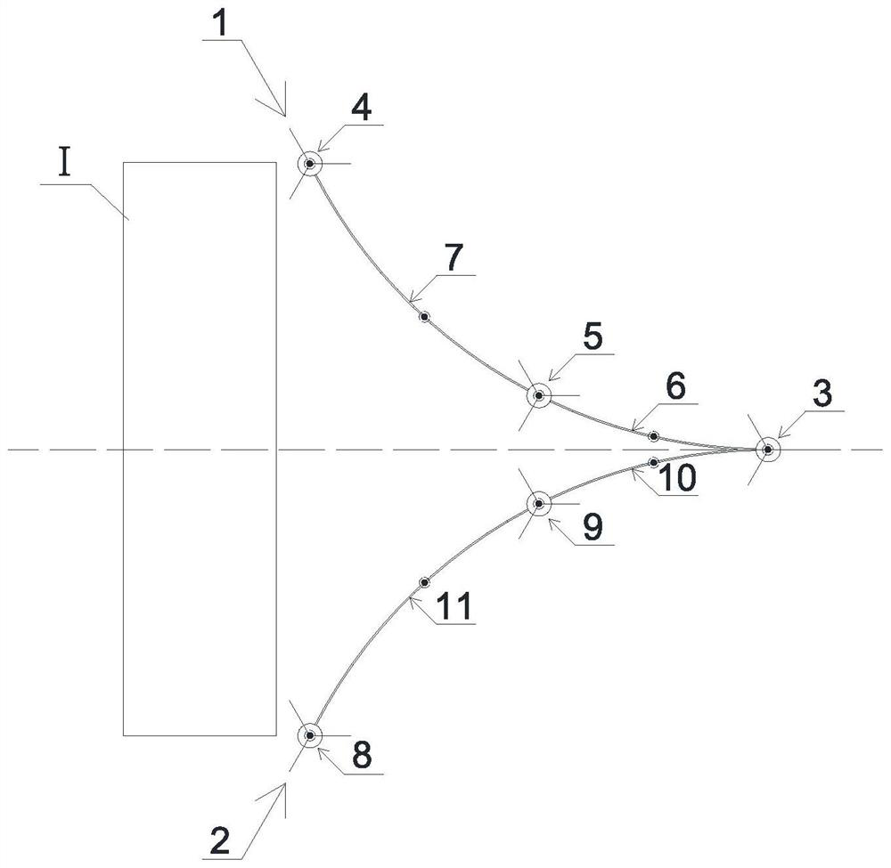
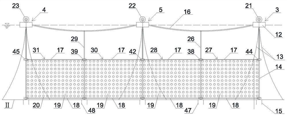
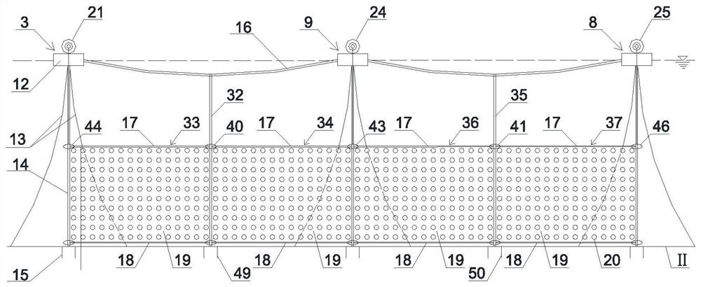
[0070] as attached Figure 1 to Figure 4 As shown, a sea current retaining wall is arranged in front of the scour improvement area I, and the sea current retaining wall includes a left retaining wall 1 and a right retaining wall 2, and the left retaining wall 1 and the right retaining wall The wall 2 is symmetrical about the center line of the scour improvement area I, the first end of the left retaining wall 1 and the first end of the right retaining wall 2 are located on the center line and form a common end, the left retaining wall The second end of the wall 1 extends from the common end to the lower left to near the left boundary of the scour improvement area I, and the second end of the right retaining wall 2 extends from the common end ...


PUM


Abstract

The invention discloses an ocean current retaining wall and a construction method thereof. The ocean current retaining wall is arranged in front of a scouring improvement area and comprises a left retaining wall body and a right retaining wall body, the left retaining wall body and the right retaining wall body are symmetrical about the center line of the scouring improvement area, the first end of the left retaining wall body and the first end of the right retaining wall body are located on the center line and form a shared end, the second end of the left retaining wall body extends from theshared end to the lower left side to the position near the left boundary of the scouring improvement area, and the second end of the right retaining wall body extends from the shared end to the lowerright side to the position near the right boundary of the scouring improvement area. A central floating body platform is arranged on the shared end; the left retaining wall body comprises a first wakeflow floating body platform, a first drainage floating body platform, a first diversion wall and a first drainage wall; and the right retaining wall body comprises a second wake flow floating body platform, a second drainage floating body platform, a second diversion wall and a second drainage wall. Reasonable flow guiding, speed limiting and soil fixing are achieved, ocean currents are guided todeviate from a wind power foundation, the flow speed of a wind power generation foundation area is effectively reduced, foundation soil keeping is enhanced, and then foundation scouring is reduced.

Description

technical field [0001] The invention relates to an anti-scouring technology for foundations of offshore wind power generation, in particular to an ocean current retaining wall and a construction method thereof. Background technique [0002] The foundation of wind power generation is easily scoured by sea currents during use, which will take away the sediment around the foundation, resulting in a decrease in the bearing capacity of the foundation and loss of stability of the inclined structure of the foundation. Therefore, the foundation needs to be protected to reduce the erosion of the foundation by tidal currents. Patent 201810328155.6 introduces an anti-scour structure for offshore wind power generation foundations. Sand and gravel are laid within a certain range around the pile foundation to form a sand scour surface, which has a good anti-scour effect in a short period of time, but there are inevitably gaps between the sand and gravel. The effect is not good under the c...

Claims


Application Information

Patent Timeline
Patent Type & Authority Applications(China)
IPC IPC(8): E02D31/00E02D27/44E02D27/52E02D5/74
CPCE02D5/74E02D27/44E02D27/52E02D31/00
Inventor 练继建李家乐任建宇董霄峰
Owner TIANJIN UNIV
Learn More