Wind power generation drive cabinet

A technology for wind turbines and cabinets, which is applied to wind turbines, combinations of wind turbines, wind turbines at right angles to the wind direction, etc. Increase the utilization rate of wind energy, high utilization rate of wind energy, and small transmission resistance

Inactive Publication Date: 2016-12-07
曹淅
View PDF5 Cites 0 Cited by
  • Summary
  • Abstract
  • Description
  • Claims
  • Application Information

AI Technical Summary

Problems solved by technology

[0002] In order to reduce environmental pollution, rational use of wind energy has been put on the agenda. Due to structural reasons, a kind of wind power drive cabinet currently used has the following defects: First, the number of blades is small, generally three, and the utilization rate of wind energy is low. ; second, the blades are made of hard materials, which vibrate violently, resulting in poor firmness; third, the blades are large in size and weight, which is not convenient for transportation and installation, especially in places such as high mountains with large wind resources. It is almost impossible to install the drive cabinet; Fourth, the generator body and brakes and other equipment are located at high places, making maintenance and repair difficult

Method used


Image

  • Wind power generation drive cabinet
  • Wind power generation drive cabinet
  • Wind power generation drive cabinet

Examples


Embodiment Construction

[0023] The structure of a wind power generation driving cabinet proposed by the present invention will be further described below in conjunction with the accompanying drawings.

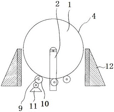
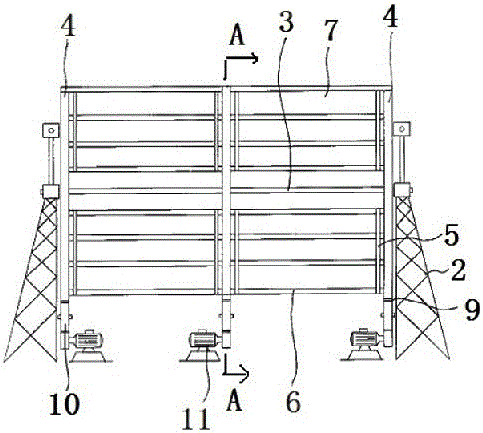
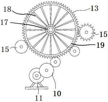
[0024] like figure 1 , figure 2 , image 3 , Figure 4 and Figure 5 As shown in FIG. 1 , it is a structural schematic diagram of a wind power generation driving cabinet. Its structure comprises wind-driven generator 1, and wind-driven generator 1 comprises support frame body 2, rotating shaft 3 and at least two runners 4 fixed with this rotating shaft 3, at least two runners 4 are arranged between adjacent runners 4. 4 The frame body 5 with the same radial direction is provided with a crossbar 6 on the frame body 5, and the crossbar 6 divides the frame body into a plurality of adjacent air inlets 7, and a windshield 8 is fixed on the peripheral side of the air inlet 7 , the runner 4 is connected to the generator body 11 through the transmission mechanism 9 and the speed change mechanism 10; a w...


PUM


Abstract

The invention belongs to the technical field of power generators, and discloses a wind power generation drive cabinet. The wind power generation drive cabinet is mainly technically characterized by comprising a wind power generator, and the wind power generator comprises a supporting frame, a rotating shaft and at least two rotating wheels fixed to the rotating shaft; at least two frames consistent with the rotating wheels in the radial direction are arranged between every two adjacent rotating wheels; the frames are provided with transverse rods, the transverse rods divide the frames into a plurality of adjacent air inlets, wind blocking sheets are fixed to the air inlets, and the rotating wheels are connected with power generator bodies through transmission mechanisms and speed change mechanisms; and wind blocking devices roughly equivalent to the rotating shaft in height are arranged on the side face of the wind power generator. During wind blowing, the wind blocking sheets and the frames located above the rotating shaft are blown, the rotating wheels are driven to rotate, the wind blocking sheets below the rotating shaft are hardly stressed under blocking of the wind blocking devices, and the rotating wheels rotate and drive the power generator bodies to rotate and generate power. The wind power generation drive cabinet is small in vibration and high in wind energy utilization rate; and the power generator bodies and a brake are all arranged on the ground, and maintaining is convenient.

Description

technical field [0001] The invention belongs to the technical field of power generation, and in particular relates to a wind power generation driving cabinet. Background technique [0002] In order to reduce environmental pollution, rational use of wind energy has been put on the agenda. Due to structural reasons, a kind of wind power drive cabinet currently used has the following defects: First, the number of blades is small, generally three, and the utilization rate of wind energy is low. ; second, the blades are made of hard materials, which vibrate violently, resulting in poor firmness; third, the blades are large in size and weight, which is not convenient for transportation and installation, especially in places such as high mountains with large wind resources. It is almost impossible to install the drive cabinet; Fourth, the generator body and brakes and other equipment are located at high places, making maintenance and repair difficult. Contents of the invention ...

Claims


Application Information

Patent Timeline
Patent Type & Authority Applications(China)
IPC IPC(8): F03D9/25F03D3/02F03D3/06F03D13/20F03D15/10F03D9/48
CPCF03D3/002F03D3/02F03D3/062Y02E10/74
Inventor 曹淅
Owner 曹淅
Why Eureka
Try Eureka