Cylinder vacuum pump
A vacuum pump, cylinder type technology, applied in the direction of pump components, rotary piston type/oscillating piston type pump components, components of pumping devices for elastic fluid, etc., can solve the problems of occupying engine output power and energy waste, etc. Achieve the effect of reducing load, saving energy consumption, and controllable working state
- Summary
- Abstract
- Description
- Claims
- Application Information
AI Technical Summary
Problems solved by technology
Method used
Image
Examples
Embodiment approach 1
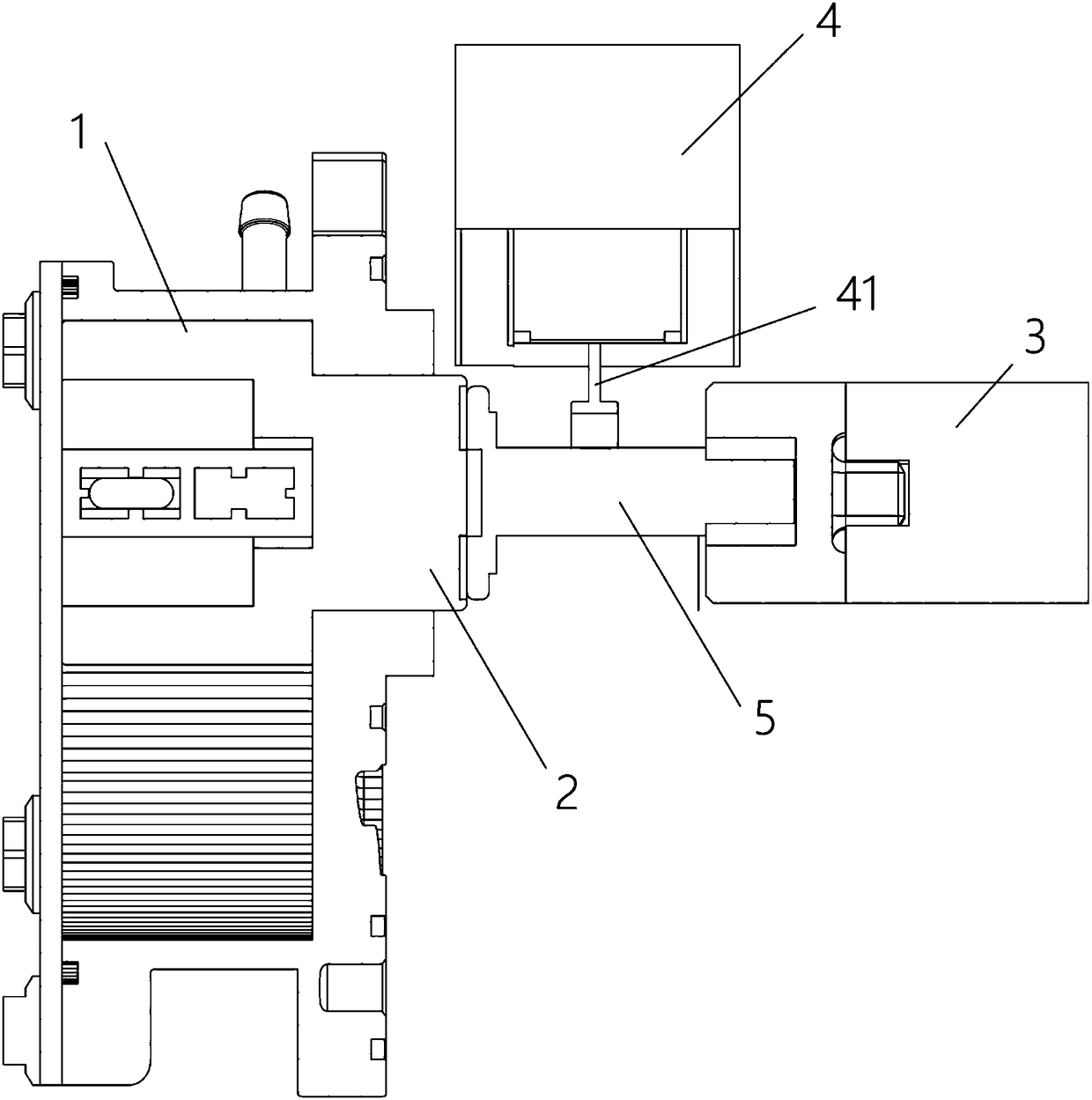
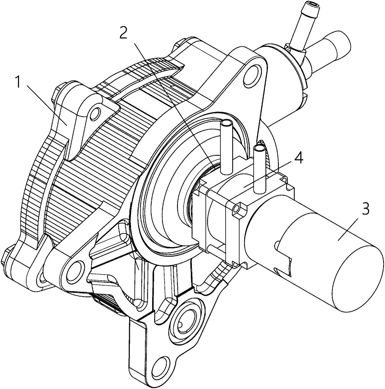
[0034] The first embodiment of the present invention provides a cylinder type vacuum pump, see figure 1 As shown, it includes a pump body 1 and a power input shaft 2 protruding from the pump body 1; the power input shaft 2 is set opposite to the power transmission shaft 3 extending from the external power mechanism; the power transmission shaft 3 rotates on its own axis Axis rotation.
[0035] In addition, the cylinder-type vacuum pump also includes a cylinder 4, which is used to control the connection or separation of the power transmission shaft 3 and the power input shaft 2; when the power transmission shaft 3 is connected with the power input shaft 2, the power transmission shaft 3 drives the power input shaft 2 to rotate , the cylinder vacuum pump works; when the power transmission shaft 3 is separated from the power input shaft 2, the cylinder vacuum pump stops working.
[0036] Specifically, in this embodiment, see figure 1 As shown, the cylinder type vacuum pump incl...
Embodiment approach 2
[0044] In the present invention, there are many ways for the cylinder 4 to push the clutch block 5 to move. In the first embodiment, the push rod protruding from the external cylinder 4 is used as an example for illustration.
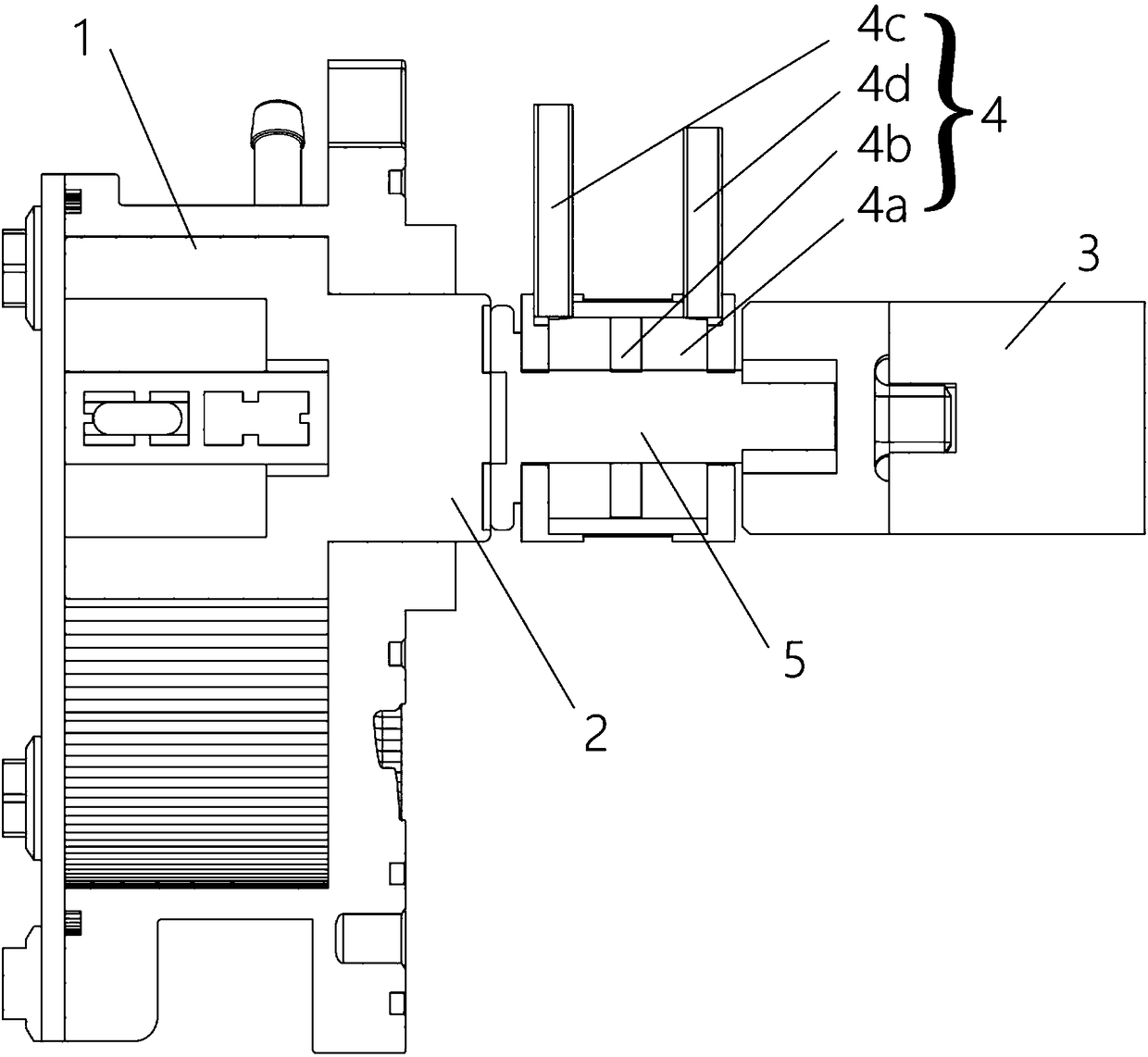
[0045] The second embodiment of the present invention provides a cylinder type vacuum pump, the second embodiment is a further improvement of the first embodiment, the main improvement is that, in the second embodiment of the present invention, see figure 2 , image 3 As shown, the clutch block 5 is at least partially located inside the cylinder 4 .
[0046] Specifically, the cylinder 4 includes a housing formed with a cavity 4a and a partition 4b disposed in the cavity 4a.
[0047] At least part of the clutch block 5 is located in the cavity 4a, and is connected with the partition 4b. The partition 4b divides the cavity 4a into two sub-cavities along the axial direction of the power input shaft 2, which are respectively the left cavity and the right ...
Embodiment approach 3
[0055] In the second embodiment of the present invention, the contact relationship between the partition 4b and the inner wall of the cavity 4a is not limited. In actual use, the space between the partition 4b and the inner wall of the cavity 4a is airtight In contact with the ground, the partition 4b can move flexibly.
[0056] The third embodiment of the present invention provides a cylinder type vacuum pump, the third embodiment is a further improvement of the second embodiment, the main improvement is that, in the third embodiment of the present invention, see Figure 4 As shown, a bearing 6 is also provided on the partition 4b. Using the bearing 6 to counteract the possible rotational movement of the partition 4b can effectively prevent the possible friction of the partition 4b against the inner wall of the cavity 4a and prolong the service life of the partition 4b.
[0057] In this embodiment, the spacer 4b may be a piston or a plastic spacer, etc., to achieve the isola...
PUM
 Abstract
Description
Claims
Application Information
 - R&D
- Intellectual Property
- Life Sciences
- Materials
- Tech Scout
- Unparalleled Data Quality
- Higher Quality Content
- 60% Fewer Hallucinations
Browse by: Latest US Patents, China's latest patents, Technical Efficacy Thesaurus, Application Domain, Technology Topic, Popular Technical Reports.
© 2025 PatSnap. All rights reserved.Legal|Privacy policy|Modern Slavery Act Transparency Statement|Sitemap|About US| Contact US: help@patsnap.com


