
Agricultural machinery engine electromagnetic clutch

An electromagnetic clutch, agricultural machinery technology, applied in non-mechanical drive clutches, magnetic drive clutches, clutches, etc., can solve the problems of complex structure, large structure size, easy damage, etc., to achieve simple operation control, compact design structure, easy to use Effort-saving effect

Active Publication Date: 2018-11-30
石家庄天人农业机械装备有限公司
View PDF7 Cites 0 Cited by
  • Summary
  • Abstract
  • Description
  • Claims
  • Application Information

AI Technical Summary

Problems solved by technology

[0003] Mechanical clutches are generally used in existing agricultural machinery to realize the clutch function. The main problems of mechanical clutches are: 1. The combined operating force is large, and the labor intensity of the driver of the harvester is high; 2. The clutch clearance needs to be adjusted regularly. The driver will not adjust it, causing the clutch to work in a semi-combined state, causing premature wear and damage to the clutch friction plate; 3. The separation shaft sleeve and shaft are prone to jamming, resulting in failure; 4. The bearing bears a large axial force during use. It is easy to be damaged; 4. The structure size is large, and the design of the whole vehicle is greatly restricted; 5. The friction plate is a vulnerable part, and it needs to be replaced every harvest season when the workload is large; 6. The structure is complex, and maintenance and adjustment require professional expertise personnel

Method used


Image

  • Agricultural machinery engine electromagnetic clutch
  • Agricultural machinery engine electromagnetic clutch

Examples


Embodiment Construction

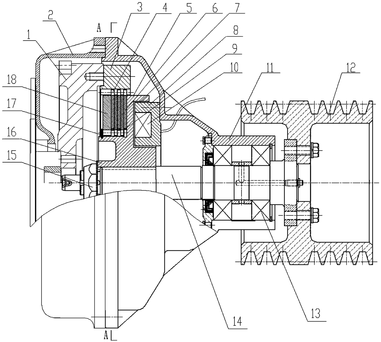
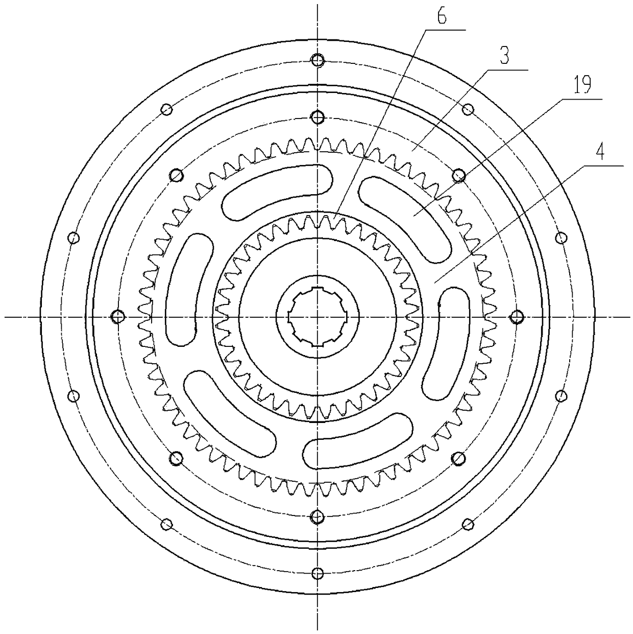
[0023] like figure 1 and figure 2 As shown, an agricultural machinery engine electromagnetic clutch related to the present invention includes a clutch housing 11 for connecting the engine flywheel housing 2, and a coil is fixed in the large-diameter port of the clutch housing 11 by screws uniformly distributed around the circumference. The sleeve 8 is provided with an annular groove on the outer end surface of the coil installation sleeve 8 and a coil 10 is packaged in the annular groove, and the two terminals of the coil 10 are drawn out from the clutch housing 11 . In the clutch housing 11, a rotatable main shaft 14 is installed through two sets of bearings 13, and a spacer sleeve is arranged between the two sets of bearings on the main shaft 14, and the large diameter end of the main shaft 14 is located in the clutch housing 11 through a spline An external gear sleeve 16 is connected, and a positioning nut 15 is connected to the outside of the external gear sleeve 16 on t...


PUM


Abstract

The invention discloses an agricultural-machine engine electromagnetic clutch. The agricultural-machine engine electromagnetic clutch comprises a clutch shell. A coil installing sleeve is fixed in the clutch shell, a coil is packaged into an annular groove in the coil installing sleeve, a main shaft is installed in the clutch shell, an outer gear sleeve is connected on the main shaft, and the inner end of the outer gear sleeve is sleeved with an inner armature; an inner gear ring is arranged in the clutch shell and used for being connected with an engine flywheel; a plurality of outer-gear friction plates and a plurality of inner-gear friction plates are arranged between the inner gear ring and the outer gear sleeve, are sequentially arranged at intervals and are engaged with teeth of the inner gear ring and teeth of the outer gear sleeve respectively, the outer end of the teeth of the outer gear sleeve is sleeved with an outer armature, and the outer armature is engaged with the outer gear sleeve through a plurality of teeth and can axially slide along the outer gear sleeve; an output belt wheel is connected to the other end of the main shaft. The agricultural-machine engine electromagnetic clutch has the advantages that operation is easy, remote control of the clutch can be achieved through an electric switch, a gap does not need to be adjusted, the fault rate is low, the service life is long, the structure size is small, and whole machine design is convenient.

Description

technical field [0001] The invention relates to an electromagnetic clutch, in particular to an electromagnetic clutch of an agricultural machinery engine. Background technique [0002] The clutch is the power output device of the agricultural machinery engine such as the harvester. Since the control operation needs to have a clutch function, it is necessary to install a clutch at one output end of the engine to realize the above functions. [0003] Mechanical clutches are generally used in existing agricultural machinery to realize the clutch function. The main problems of mechanical clutches are: 1. The combined operating force is large, and the labor intensity of the driver of the harvester is high; 2. The clutch clearance needs to be adjusted regularly. The driver will not adjust it, causing the clutch to work in a semi-combined state, causing premature wear and damage to the clutch friction plate; 3. The separation shaft sleeve and shaft are prone to jamming, resulting i...

Claims


Application Information

Patent Timeline
Patent Type & Authority Patents(China)
IPC IPC(8): F16D27/115
CPCF16D27/115
Inventor 成东江姚志军
Owner 石家庄天人农业机械装备有限公司
Learn More