
Valve mechanism for stevia confectionery powder processing

A valve and candy technology, applied in the valve shell structure, lift valve, valve details, etc., can solve the problems of low drying efficiency, low discharge efficiency, easy to stay in, and achieve large discharge area and high discharge efficiency. , open the effect of high success rate

Active Publication Date: 2018-10-16
XINGHUA GL STEVIA CO LTD
View PDF7 Cites 0 Cited by
  • Summary
  • Abstract
  • Description
  • Claims
  • Application Information

AI Technical Summary

Problems solved by technology

[0003] In the patent of invention with the patent number ZLCN201310678847.0, the applicant of this case discloses a processing device that integrates independent drying and milling equipment. Nutrients and unique flavors can be continuously produced in a flow-type manner during the milling process without generating dust and affecting the production environment; however, the above-mentioned processing device has the following problems: when the friction between the material and the drying plate is large, the material is easy to It stays on the drying plate all the time, resulting in low drying efficiency; the discharge valve is composed of a relatively rotating valve seat and valve core. When the valve is opened, there is still a nearly half area of ​​the blocking surface, and the discharge efficiency is low; the crushing mechanism only exists A set of grinding discs, the crushing effect is not ideal

Method used


Image

  • Valve mechanism for stevia confectionery powder processing
  • Valve mechanism for stevia confectionery powder processing
  • Valve mechanism for stevia confectionery powder processing

Examples


Embodiment Construction

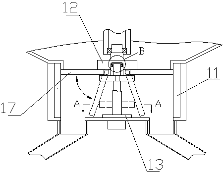
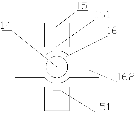
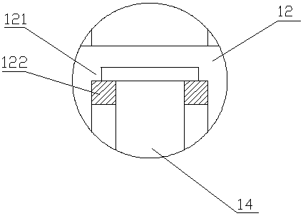
[0014] Such as figure 1 and figure 2 As shown, the valve mechanism used for stevia candy powder processing in this embodiment is installed at the discharge port at the bottom of the drying box. The valve mechanism includes a housing 11, an upper seat plate 12, a lower seat plate 13, a screw rod 14, a bracket 15, and a nut 16 and two opposite semicircular valves 17, the housing 11 is connected to the bottom of the drying box, the upper seat plate 12 and the lower seat plate 13 are respectively arranged at the upper end and the lower end of the inner cavity of the housing 11, and the screw rod 14 is vertically arranged on the shell The center position of the inner cavity of the body 11, and the upper and lower ends are respectively rotatably connected to the upper seat plate 12 and the lower seat plate 13, and the two valves 17 are respectively arranged on both sides of the screw rod 14 and symmetrically hinged on the bottom of the upper seat plate 12. Protrusions 161 are resp...


PUM


Abstract

The invention discloses a valve mechanism for processing stevioside fruit powder. The valve mechanism is mounted at a discharging opening in the bottom of a drying box and comprises a shell, an upper seat plate, a lower seat plate, a threaded rod, two valves, sliding grooves and a nut. The shell is connected to the bottom of the drying box. The upper seat plate is arranged at the upper end of an inner chamber of the shell, and the lower seat plate is arranged at the lower end of the inner chamber of the shell. The threaded rod is vertically arranged in the center of the inner chamber of the shell. The upper end of the threaded rod is connected to the upper seat plate in a rotary manner, and the lower end of the threaded rod is connected to the lower seat plate in a rotary manner. The two valves are arranged at the two sides of the threaded rod correspondingly and symmetrically hinged to the bottom of the upper seat plate. The two sides, in the radial direction, of the nut are each provided with a protruding block, and the two sides in the radial direction perpendicular to the radial direction are each provided with a push plate extending in the direction of the corresponding valve. The two sliding grooves are formed in the two sides of the threaded rod correspondingly and correspond to the positions of the protruding blocks on the nut. The nut is connected to the threaded rod in a rotary manner, and each protruding block is connected into the corresponding sliding groove in a sliding manner. The valve mechanism is large in discharging area.

Description

technical field [0001] The invention relates to plant crushing and processing equipment, in particular to a valve mechanism for processing stevia candy powder. Background technique [0002] In order to change the bitter taste of stevia, the applicant in this case designed a fruit-flavored compound sweetener, which used fruit powder, such as blueberry fruit powder, so the production of sweeteners involves the drying and milling of fruit plants. [0003] In the patent of invention with the patent number ZLCN201310678847.0, the applicant of this case discloses a processing device that integrates independent drying and milling equipment. Nutrients and unique flavors can be continuously produced in a flow-type manner during the milling process without generating dust and affecting the production environment; however, the above-mentioned processing device has the following problems: when the friction between the material and the drying plate is large, the material is easy to It s...

Claims


Application Information

Patent Timeline
Patent Type & Authority Patents(China)
IPC IPC(8): F16K31/04F16K1/36F16K1/02F16K27/02
CPCF16K1/02F16K1/36F16K27/02F16K31/042
Inventor 周伯雅
Owner XINGHUA GL STEVIA CO LTD
Learn More